EasyManua.ls Logo

Grasslin DTMV40 Series - User Manual

Grasslin DTMV40 Series
6 pages
Print Icon
To Next Page IconTo Next Page
Loading...
• Disconnectpoweratthecircuitbreaker(s)ordisconnectswitch(es)beforebeginning
installationorservicing.
• Morethanonecircuitbreakerordisconnectswitchmayberequiredtode-energizethe
equipmentbeforeservicing.
• Donotusethemanualoffpositionofthetimerforequipmentservicing.Alwaysdiscon-
nectthepoweratthecircuitbreaker(s)ordisconnectswitch(es).
• UseCOPPERconductorsONLY.
• For40amploads,use#8AWGwire,rated90˚Cmin.
• Wireinaccordancewithnationalandlocalelectricalcoderequirements.
DTMV40 Series
TimeInitiated,Temperature,
PressureorTimeTerminatedMulti-Voltage
40ADefrostTimers
WARNING
Risk of Fire or Electric Shock
• Rotatetimerdialclockwiseonly.
CAUTION
Risk of Damage to Timer
1
Paragon Precision
TIME INITIATED, TIME TERMINATED
Grasslin
Mode Selection Wiring Diag.
TIME INITIATED, PRESSURE TERMINATED
(Separate Pressure Switch Required (see instructions)
TIME INITIATED, REMOTE TEMPERATURE OR
PRESSURE TERMINATED
STARTUP PROCEDURE
1. Determine model to be replaced (Grasslin or Competitors)
from table below.
2. Set Mode Selection (S1 BLUE DIP Switch
Fig. A) See table below and instructions
on page 5.
3. Apply corresponding Terminal
Identification and Door labels –see retrofit
kit instructions.
4. Set correct input voltage (S2 RED DIP
Switch – Fig. B).
5. Follow installation and programming instructions.
The DTMV40 can be configured for
either 120 or 208/240VAC. Locate RED
DIP Switch to the right of timer module.
For:
120VAC slide DIP switch UP
208/240VAC slide DIP switch DOWN
TImer Mechanism
Step 2
Interior
Protective
Cover
Step 1
Ground Lug
2-1/2”
6-1/8”
INSTALLATION
Note: For outdoor locations, raintight, or wet location conduit
hubs that comply with requirements of UL 514B (standard for
fittings for conduit and outlet boxes) are to be used.
1. Open door and then remove interior protective cover by
releasing spring clip on bottom.
2. Remove timer mechanism by releasing spring clip on bot-
tom.
3. Select knockouts to be used. Remove inner 1/2” knockout
by inserting a screwdriver in the slot and carefully punch
knockout loose. Remove slug. If 3/4” knockout is required,
remove the outer ring with pliers after removing the 1/2”
knockout. Smooth edges with knife if necessary.
4. Place enclosure in desired mounting location and mark the
three mounting holes (refer to diagram below). Start by
placing set screw on top and attaching enclosure over
keyhole: then screw in remaining two screws on bottom.
5. Connect conduit hubs to conduit before connecting the
hubs to the enclosure. After inserting hubs into enclosure,
carefully tighten hub lock nut. Do not over-torque.
6. Verify voltage selection. 120VAC position switch UP;
208/240VAC – position switch DOWN (refer to Fig. B).
7. Wire in accordance with National and Local
Codes.
8. Gr
ounding: Terminate all ground wires to ground lug on
bottom of enclosure.
9. Replace interior pro-
tective cover.
UL TYPE 3R Enclosure
Bracket Mount
Input Voltage Switch (S2)
Mode Selection Switch (S1)
http://waterheatertimer.org/Intermatic-Defrost-timers-and-manuals.html
Question and Answer IconNeed help?

Do you have a question about the Grasslin DTMV40 Series and is the answer not in the manual?

Summary

OPERATING INSTRUCTIONS

WARNING Risk of Fire or Electric Shock

Critical safety precautions regarding electrical hazards during installation and servicing.

CAUTION Risk of Damage to Timer

Important caution for preventing damage to the timer during operation.

STARTUP PROCEDURE

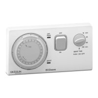
Step-by-step guide for initial setup and model determination.

INSTALLATION

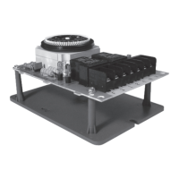
Instructions for mounting the enclosure and wiring the unit.

Model Designation

Enclosure Mount Models

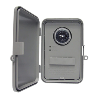
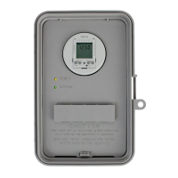
Lists DTMV40 models with different enclosure types.

Non-Enclosure Mount Models

Lists DTMV40 models without enclosures.

PROGRAMMING AND OPERATION

Setting the Time

Instructions on how to set the current time on the timer dial.

Setting Defrost Initiation Time

Guide on setting specific times for defrost cycles.

Setting Maximum Defrost Duration

How to configure the length of each defrost cycle.

DTMV40 TROUBLESHOOTING GUIDE

Mode A: Refrigeration and Defrost

Troubleshooting steps for Mode A refrigeration and defrost cycles.

Mode B: Refrigeration and Defrost

Troubleshooting steps for Mode B refrigeration and defrost cycles.

TYPICAL WIRING DIAGRAMS

8045 Replacement Wiring

Wiring diagram for replacing model 8045.

8145 Replacement Wiring

Wiring diagram for replacing model 8145.

8143 Replacement Wiring

Wiring diagram for replacing model 8143.

8245 Replacement Wiring

Wiring diagram for replacing model 8245.

8243 Replacement Wiring

Wiring diagram for replacing model 8243.

120 V Fan & 240 V Compressor Wiring

Wiring diagram for mixed voltage fan/compressor.

WIRING LEGENDS

TIME INITIATED, TIME TERMINATED Legend

Legend for time-initiated, time-terminated models.

REMOTE TEMPERATURE;PRESSURE TERMINATED Legend

Legend for time-initiated, temp/pressure-terminated models.

PRESSURE TERMINATED Legend

Legend for time-initiated, pressure-terminated models.

APPLICATION

DTMV40 Application Details

Explains timer function for various termination methods.

F Terminal Functionality

Description of the 'F' terminal's functionality.

REPLACING EXISTING DEFROST TIMERS

Terminal Identification for Replacement

Details on terminal identification for replacement.

Mode Selection (Light Blue DIP Switch)

Guide to selecting the correct mode switch setting.

Specific Model Replacement Notes

Instructions for replacing specific models like 8143, 8240, 8045.

SPECIFICATIONS

Maximum Contact Switch Rating

Electrical ratings for the timer's contacts.

F Terminal Rating

Electrical rating for the 'F' terminal.

Wiring Connections and Environmental Ratings

Information on wiring connections and operating environment.

Electrical Life, Dimensions, Weight, and Approvals

Details on electrical lifespan, physical size, weight, and approvals.

Product FEATURES

Broad Replacement Capability

Highlights the timer's compatibility with over 40 models.

Multi-Voltage and Easy Installation

Field adjustable voltage and tool-less mounting.

Defrost Timing and Capacity

Precise defrost timing and high load capacity.

Durability and Usability Features

Includes outdoor enclosure, coated board, and LED indicators.

SPECIFIERS GUIDE

Defrost Control Requirements

Requirements for specifying the DTMV40 defrost control.
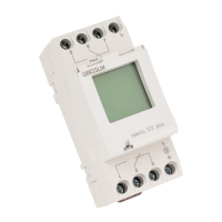
Grasslin DTMV40 Series Specifications

General IconGeneral
Mounting TypeDIN Rail
Contact ConfigurationSPDT
Voltage230V AC
Number of Channels1
Timing Range1 min to 168 hours
DisplayLCD
Protection RatingIP20

Related product manuals