EasyManua.ls Logo

Grasslin Digi 20A - User Manual

Grasslin Digi 20A
4 pages
Print Icon
To Next Page IconTo Next Page
Loading...
Digi 20 Series
One Circuit Electronic
24 Hour or 7 Day Time Switches
Digi 20A
(surface mounting)
Digi 20E
(flush mounting)
APPLICATION
Time based control of lighting, ventilating, heating, cooling
or other electrical loads in commercial and industrial applica-
tions. The Digi 20 time switches are programmable for 24-
hour or 7-day schedules.
The Digi 20A is intended for either surface or rail mounting.
The control is completely enclosed in a plastic housing and
includes a terminal cover and sub-base for installation and
hard wiring.
The Digi 20E is intended for flush (panel) mounting.
All units are supplied with a clear plastic dust cover. They
are also available with an enclosure for stand-alone applica-
tions. (GM and GMX models)
TECHNICAL DATA
Output–1 SPDT relay with dry contacts
Switch Rating: 16A/277VAC resistive
1000W tungsten @ 240VAC; 500W @ 120VAC
1/2 hp @ 120VAC; 1 hp @ 240VAC
100 hour capacitor back-up of memory and display
Supply voltages: Separate Models – 24VAC/DC, 120VAC,
208/240VAC, all 50/60Hz (refer to product label)
Shortest switch time–1 minute
Ambient Temperature Range –20°F to 140°F (–28°C to 60°C)
VA required: 120V & 240V models: 4VA
24V model: 2VA @ 24VAC, 1VA @ 24VDC
Screw terminal connections (Digi 20A)
1/4” quick connects (Digi 20E)
Accuracy ± 4 minutes per year
Installation
To the installer:
1. Read operating instructions carefully.
2. Check the input and output ratings marked on the unit
to
make sure this product is suitable for your power supply
and application.
3. Disconnect power supply prior to installation to prevent
electrical shock.
4. Wire in accordance with National and Local electrical code
requirements.
SURFACE MOUNTING—Digi 20A
Remove dust cover, loosen two screws on opposite corners.
Remove the housing that surrounds the time switch and the
terminal cover away from the base. Remove timer module by
pulling straight out.
Place screws through 3 mounting holes in base and screw
to back panel or wall.
Wire in accordance with instructions. Replace terminal cover
and push timer firmly onto base. Now replace housing and
secure with screws.
NOTE: The Digi 20A is also suitable for DIN rail mounting.
Break out housing part on each side that fits over rail.
PANEL MOUNTING—Digi 20E
Cut a square hole 2-5/8” x 2-5/8” (66mm x 66mm) in the front
of the panel. Insert the time switch through the opening. With
a screwdriver, press down and turn outer screws (A) until
flanges are in position to fasten the unit in front panel, then
release. Insert plugs into holes (B).
Use 1/4” quick connects and make connections in accor-
dance with the wiring diagram shown and applicable code
requirements.
WIRING
1. Disconnect the power.
2. Wire input to timer, , with the
proper voltage marked on the
unit. Wiring to incorrect voltage
will void the warranty.
3. Connect wiring according to the
wiring diagram. The terminals on
the Digi 20A sub-base will accom-
modate 10 to 24 AWG wire.
M
LOAD
POWER
TIMER INTERNAL WIRING
COM NO NC
TIME
SWITCH
FIELD WIRING
1 2 3 4 5
Terminal Connections
B
A
A
B
C
FILE: E83486
http://waterheatertimer.org/Intermatic-timers-and-manuals.html
For updated timers and manuals
Question and Answer IconNeed help?

Do you have a question about the Grasslin Digi 20A and is the answer not in the manual?

Summary

Product Overview and Mounting

Surface Mounting Digi 20 A

Instructions for removing the dust cover, housing, and terminal cover for surface mounting.

Panel Mounting Digi 20 E

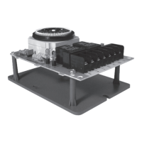
Steps for cutting a panel hole and securing the time switch using flanges.

Application

Details the use of Digi 20 time switches for commercial and industrial applications.

Technical Data

Provides specifications like switch rating, supply voltages, and ambient temperature range.

Installation and Wiring Procedures

Installation Steps

Guides for installers on reading instructions, checking ratings, and disconnecting power.

Wiring Instructions

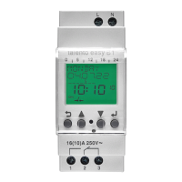
Steps for wiring the timer, including voltage connection and wire gauge for Digi 20A.

Using the Digi 20 Time Switch

Keypad Description

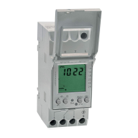
Explanation of keypad buttons like Prog, Res, ±1h, h, m, and Day.

LCD Display Elements

Description of icons and indicators on the LCD screen such as time, day, and ON/OFF symbols.

Programs Explained

Details on how programs are structured, including ON/OFF commands and day selections.

Setting Time and Modes

Instructions for setting the current time, AM/PM or military time, and daylight saving.

Programming and Troubleshooting

Programming Schedules

Guidance on creating 24-hour or 7-day schedules with ON/OFF events and specific times.

Day Key Selections

Table showing how to select specific days or ranges of days for programmed events.

Manual Override

How to temporarily or continuously override the current schedule.

Changing and Deleting Programs

Procedures for modifying or removing existing programmed events.

Troubleshooting Common Issues

Solutions for problems like flashing days, loss of program, or output not activating.

Other Grasslin Time Control Products

MIL 72 Series

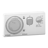
Electromechanical 24-hour & 7-day time switches with similar configurations to Digi 20.

GM & GMX Series

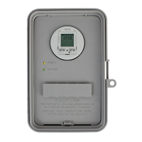
Mechanical & electronic 24-hour and 7-day time switches in NEMA enclosures.

KM2 In-Wall Timer

A 24-hour or 7-day timer that replaces standard wall switches.

Frost King Refrigeration Defrost Timers

Defrost timers designed to replace standard models in refrigeration units.

Digi 42; Digi 42;2

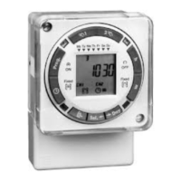
7-day electronic time switches with single or dual channels.

Digi 322

Programmable 365-day electronic time control with multiple channels.

KLT 2005 Countdown Timer

Mechanical spring wound timer for mounting in electrical boxes.

Grasslin Digi 20A Specifications

General IconGeneral
TypeDigital Timer
Max Load16A
Voltage230V AC
DisplayLCD
Battery BackupYes
Number of Channels1
Mounting TypeDIN Rail
Operating Temperature-10°C to +40°C
WeightApprox. 150g

Related product manuals