13 / 24
16570.123_V1sh
• STM32 F405 MCU, Runs Betaflight irmware(supported from v3.2)
• MPU6000 Over SPI Bus
• 20x20mm Mounting holes
• Supports Lipo direct plugin (3-6S)
• Supports 5V 1A BEC output(Buck), Max 2A
• STM32 controls OSD chip over SPI in DMA mode(Betaflight OSD)
• Incl. Baro BMP280
• 6x PWM output
• 3x UARTs
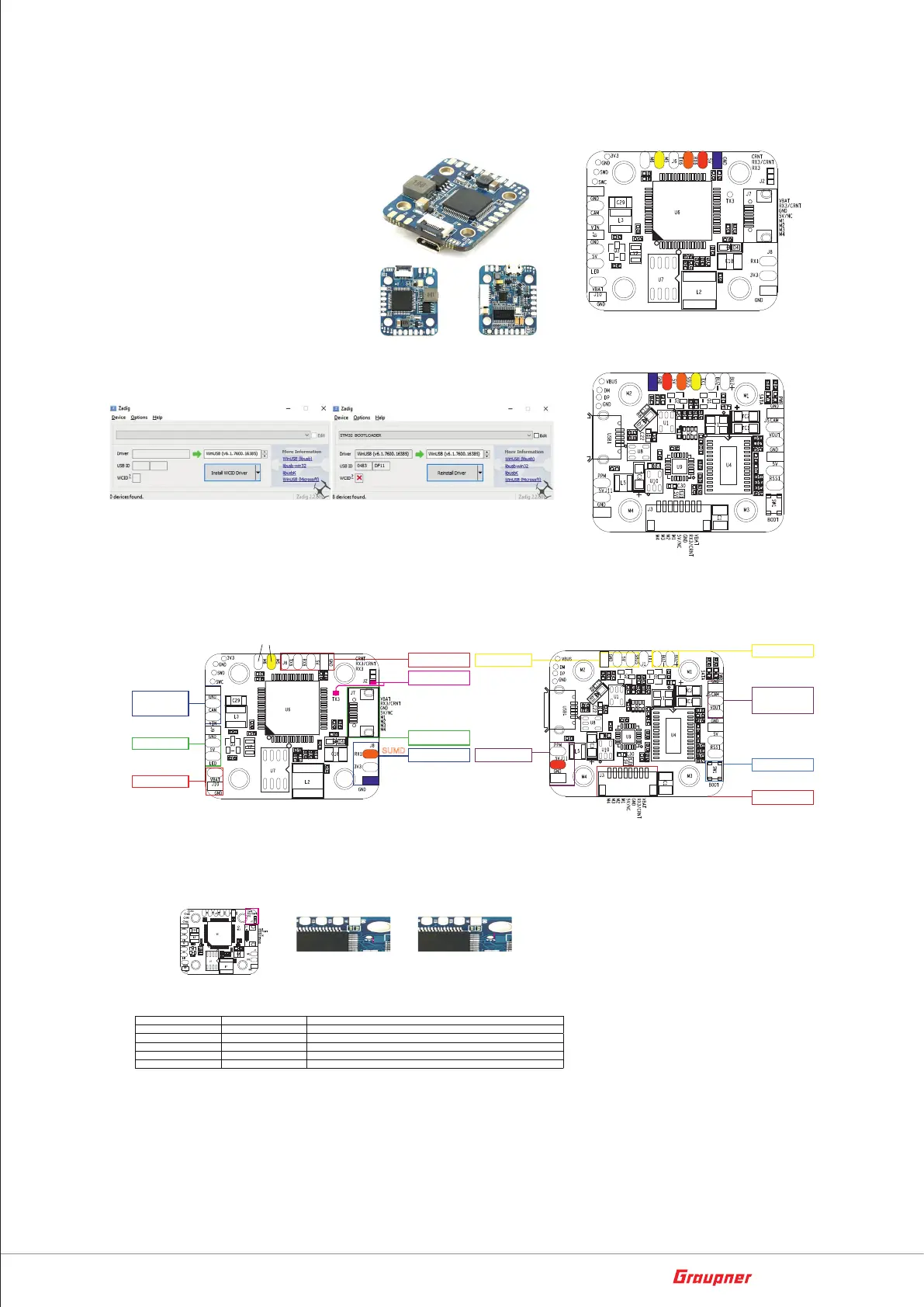
OMNIBUS F4 Nano V5
Pinmap
The Omnibus F4 NANO V5 flight controller using MPU 6000 gyro and
STM32 F405 MCU, with upgraded BEC design, it works up to 6S. other
important features include BetaFlight conigurable OSD, barometer.
The redesigned 4in1 port supports ESC telemetry function now, there
is one jumper for setup the current source, for example, ADC or ESC
telemetry.
Firmware update
OMNIBUS has been supported by Betaflight v3.2, you can use Target "OMNIBUSF4SD" to update the irmware.
How to use the onboard USB port updated irmware in GUI on windows
To Flash the Firmware you have to enter the so called DFU mode. On Windows 10 I had to use a tool called Zadig (download and start it) to be able to switch
drivers for DFU mode to work. In order to switch drivers you have to take the following steps.
* Pictures and text made by : Aerosufer
http://www.aerosurfer.ch/2016/07/25/omnibus-f3-flight-controller/
• Push BOOT button on the Flight controller.
• Plug-in the USB cable (the red LED should not be as bright as normally).
• Fire up Zadig and hit “Options” and then “List All Devices”.
• From the list choose “STM32 BOOTLOADER”.
• Under “Driver” choose “WinUSB” on the right and hit “Reinstall Driver”.
• Close Zadig, disconnect the Flight controller, close all Google Chrome instances.
48374.Nano Omnibus Nano F4 V5
connection SBUS+ HoTT Telemetry
connection HoTT Telemetry on Softserial and
RX serial on RX6
PPM input
Boot 0
Button
SBUS
UART 1
WS2812B
LED Strips
PWM 1-4
4in1 FPC socket
UART3
Could be used as IIC
UART 6 with 5v
PWM 1-4
4in1 ESC Socket
Camera
CAM pin supplies 5V
though onboard LC ilter
VTX
CAM pin supplies 5V
though onboard LC ilter
Connection example
Jumpers
Resources:
The Omnibus F4 NANO V5 includes a current source selection jumper (see below for setup details):
If you are using 4in1 ESC board, like ORI32 and it is connected using the 8 pin Sh1.0 Socket, you need to choose between RX3 (to receive ESC telemetry) or
CRNT (ESC current meter sensor) by jumping J2 middle pin (RX3/CRNT) with upper pin (RX3) or lower pin (CRNT) as indicated in red in the image below.
J2 J2 - RX3 J2 - CRNT
SBUS UART1
DSM2 UART1
Please use another UART if RX1 used for ESC telemetry function
Smart Audio VTX UART6
Smartport TX1
TX1: Enable as software serial, then bidirectional
ESC Telemetry UART3
RX3
IIC UART3
Disabled ESC Telemetry functioin irst
LIPO input
3-6S
Buzzer
48374.Nano Omnibus Nano F4 V5
Connection GPS on UART6,
HoTT-Telemety on softserial 1 (betaflight)
Smart/Audio on softserial 2 (betaflight)
SUMD on UART1 RX
softserial for HoTT-Telemetry and Smart/Audio
GPS
SUMD
SUMD, DSM2
UART1 RX