GRAUPNER GmbH & Co. KG D-73230 KIRCHHEIM/TECK GERMANY
We reserve the right to introduce modifications. Not liable for printing errors!
11/2011
- 4 -
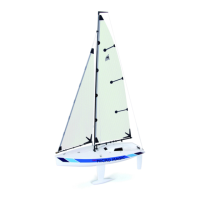
The figure shows the completed aileron connection. Note that the length of the servo
levers should be a minimum of 14 mm to keep the clevis
from colliding with the wing.
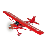
The figure shows the completed landing flap connection. Note that the length of the
servo levers should be a minimum of 12 mm to keep the clevis
from colliding with the wing.
Note: Arrange the spreading landing gear so that the flap deflection is about 12 mm
with the servo in neutral position, as shown here. Set the full deflection to about 25
mm. It is best to operate the flaps on the transmitter with a 3-stage switch. The
asymmetrical servo arrangement makes it possible later to control both servos
without a mixer with a connector cable Order No. 3936.32 at one of the transmitter
outputs.
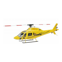
The figure shows the servo lead exiting at the wing root. Later, use the CRP tube Ø
5x125 mm to push the halves of the wing onto the fuselage.

 Loading...