GRAUPNER GmbH & Co. KG D-73230 KIRCHHEIM/TECK GERMANY
We reserve the right to introduce modifications. Not liable for printing errors!
11/2011
- 5 -
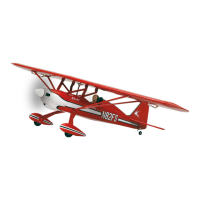
Fuselage with tail group and cockpit canopy
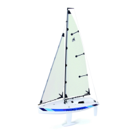
First place the motor spindle, motor mount, and locking ring onto the motor; these
parts are included as accessories in the package for Order No. 7738.
The figure shows the individual parts for the motor spindle and motor mount; tighten
all screws.
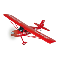
The figure shows the motor with attached motor mount and motor spindle. Separate
the motor leads and remove about 5 mm of insulation. Apply solder to the ends of all
leads and then solder on the G 3.5 connectors (included with Order No. 7738);
insulate the connector shaft with the heat-shrink sleeves (included with Order No.
7738). Use a hair dryer to shrink the heat-shrink sleeve. Then do a test run of the
motor. Viewed in flight direction, the motor should rotate to the right; if this is not the
case, switch any two of the leads and re-insert.

 Loading...