GB - 25
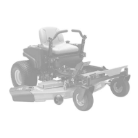
2. Adjust Steering Lever Width
1. Loosen hardware at the base of the
lower control arm item 5.
2. Rotate eccentric spacer to move the
leve
rs away from or closer to the
operators position (figure 21).
3. Adjust Steering Lever Forward or
Backward
1. Loosen, do not remove, the bolts
securing the handlebar to the upper
control arm.
2. Slide steering lever forward or backward
to de
sired position and tighten bolts.
NOTE: T
ighten upper bolt first.
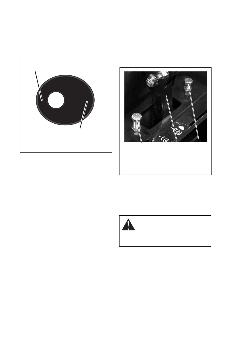
Forward and Reverse Speed
Adjustment
(Figure 22)
IMPORTANT: The un
it should track within
2 feet (0.610.61 m) of a straight line for 30
feet (9.14 m).
The travel of the steering levers may need
adjustmen
t if:
• The unit turns to the right or left when
both
steering levers are pushed as far
forward as possible.
• The unit turns to the right or left when
both steer
ing levers are pulled back as
far rearward as possible.
NOTE: T
he side the unit turns toward
indicates that the wheel on that side is turning
slower than the other wheel. Either the wheel
that is turning faster needs to slow down or
the wheel that is turning slower needs to be
sped up to allow the unit to travel in a straight
line.
1. Determine which way the unit turns.
NOTE: The for
ward travel adjustment bolt
adjusts the rear travel of the steering lever.
The rear travel adjustment bolt adjusts the
forward travel of the steering lever.
2. Adjust speed by loosening jam nut and:
• Turning adjustment bolt clockwise to
decrease steering leve
r travel.
• Turning adjustment bolt counter
clockw
ise to increase steering lever
travel.
REPLACING PTO BELT
Remove
(Figure 23)
1. Lower mower deck to the ground.
2. Remove belt covers from mower deck.
3. Hook a puller into idler hole and pull idler
ar
m towards outside of unit until tension
is removed from PTO belt.
Figure 21
Rotate this end away from the operator
position to move the steering levers out.
Rotate this end away from the operator
position to move the steering levers in.
Eccentric Spacer
CAUTION: Use care when
releasing idler spring tension.
Keep body parts well away from
idler when performing this
operation.
Figure 22
3
1
2
1. Forward Travel Adjustment Bolt
2. Rear Travel Adjustment Bolt
3. Lower Control Arm