EN - 17
Parking Brake Interlock System
With the parking brake engaged, the steering
levers must be locked in neutral.
With the parking brake disengaged, the
engine must not start and the engine must
shut off if the operator lifts from the seat.
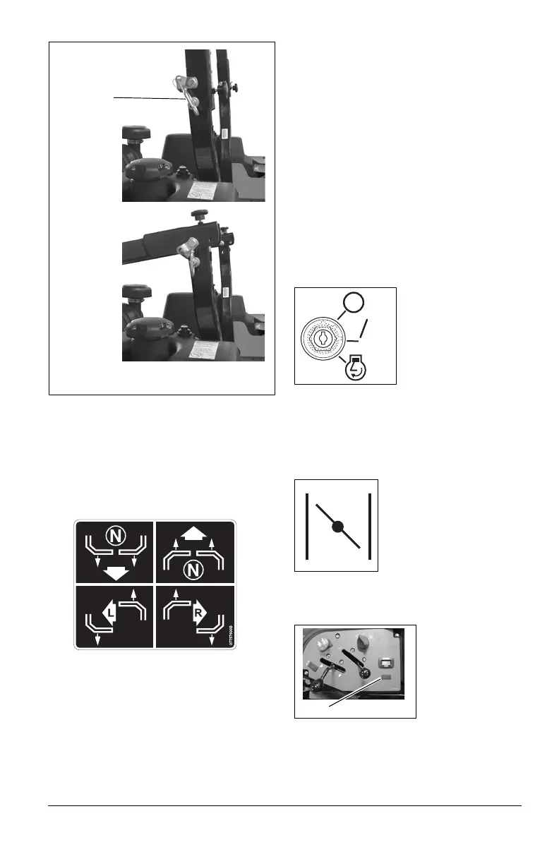
Steering Levers
The steering levers control speed and
direction. In addition, they will stop the unit.
A. For reverse travel, pull both steering
control levers backward.
B. For straight forward travel, push both
steering control levers forward.
C. To turn left, pull the left back or push
the right steering control lever forward
or a combination of both.
D. To turn right, pull the right back or
push the left steering control lever
forward or a combination of both.
To stop, return both steering levers to neutral.
NOTICE: The steering controls are
mechanically locked in neutral whenever the
parking brake is engaged.
NOTICE: Aggressive turning can scuff or
damage lawns. ALWAYS keep both wheels
rotating when making sharp turns. DO NOT
make turns with inside wheel completely
stopped. To obtain minimum turning radius,
slowly reverse inside wheel while moving
outside wheel slowly forward.
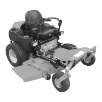
Ignition Switch
Operate the ignition
switch with the
removable key. The
switch has three
positions:
•Off (1)
•On (2)
•Start (3)
To start the engine, turn the key to Start, then
release to On. To stop the engine, turn the
key to Off.
Choke Control
(992230, 234, 235, 239, 244, 245)
Push the choke lever
forward (On) to close the
choke and start a cold
engine.
Pull the choke lever to the
rear (Off) to open the
choke after the engine
warms.
Malfunction Indicator Light
(992224, 225, 231, 233)
The fuel injection
system is
monitored by an
electronic control
unit (ECU). If a
fault or malfunction
is detected in the
fuel management
system the ECU
will generate a signal and the Malfunction
Indicator Light (MIL) (item 1) will illuminate.
See your Dealer for diagnostics and repair.
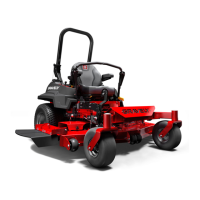
Lowered
Position
Figure 5
Raised
Position
1. Lock Pin
1