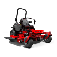
EN - 31
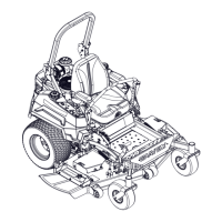
Remove Hydro Pump Belt
See Figure 38.
1. Using a spring puller, slowly remove
spring from anchor bolt until all tension is
removed.
2. Remove and retain the clutch anchor and
mounting hardware.
3. Remove and retain clutch stop and
mounting hardware.
4. Remove hydro pump belt.
Install Hydro Pump Belt
See Figure 38.
IMPORTANT: Hydro pump belt MUST be
installed before PTO belt.
1. Install hydro pump belt around sheaves.
Route belt according to the decal located
on the bottom of the floor pan.
2. Reinstall clutch stop and mounting
hardware. Tighten hardware to
18N•m –23N•m (13lb-ft –17lb-ft).
3. Reinstall PTO Belt. See Install PTO Belt
on page 31.
IMPORTANT: Verify that there are no twists
in belts and that they are routed correctly.
4. Close belt access panel and reinstall belt
covers.
Install PTO Belt
1. Install PTO belt around deck sheaves.
Route belt according to the decal located
on the bottom of the floor pan. See
Figure 37.
IMPORTANT: Verify that there are no twists
in belts and that they are routed correctly.
2. Close belt access panel and reinstall belt
covers.
CAUTION: Use care when
releasing idler spring tension.
Keep body parts well away
from idlers when performing
this operation.
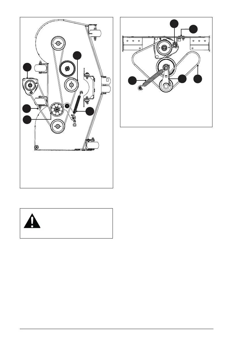
Figure 37
1. PTO Mower Belt
2. Spring
3. PTO Mower Belt Idler
4. Mower Clutch Sheave
5. Center Sheave
3
1
4
2
5
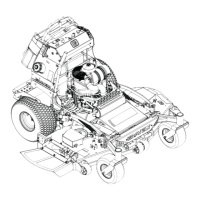
1. Hydro Belt
2. Spring
3. Idler
4. Clutch Anchor
5. Clutch Stop
1
2
3
4
5
Figure 38