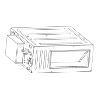
Multi Variable Air Conditioners Ducted Type Indoor Unit
9
4.3 Drainage Line Installation and Drainage System Testing
4.3.1 Notice for Installation of Drain Line
(1) The drain line should be short and the downward slant should be at least
1%~2% in order to drain condensation properly.
(2) The diameter of drain line should be greater than or equal to the diameter of drain
connection.
(3) Install drain line according to the following fig. and secure insulation to the drain line (Fig
4.3.1). Improper installation may lead to water leakage and resulting damage.
(4) Hard PVC pipe may be used as the drain line. When connecting, insert the end of PVC
pipe into the drain hole and secure it. Do not use glue (PVC cement).
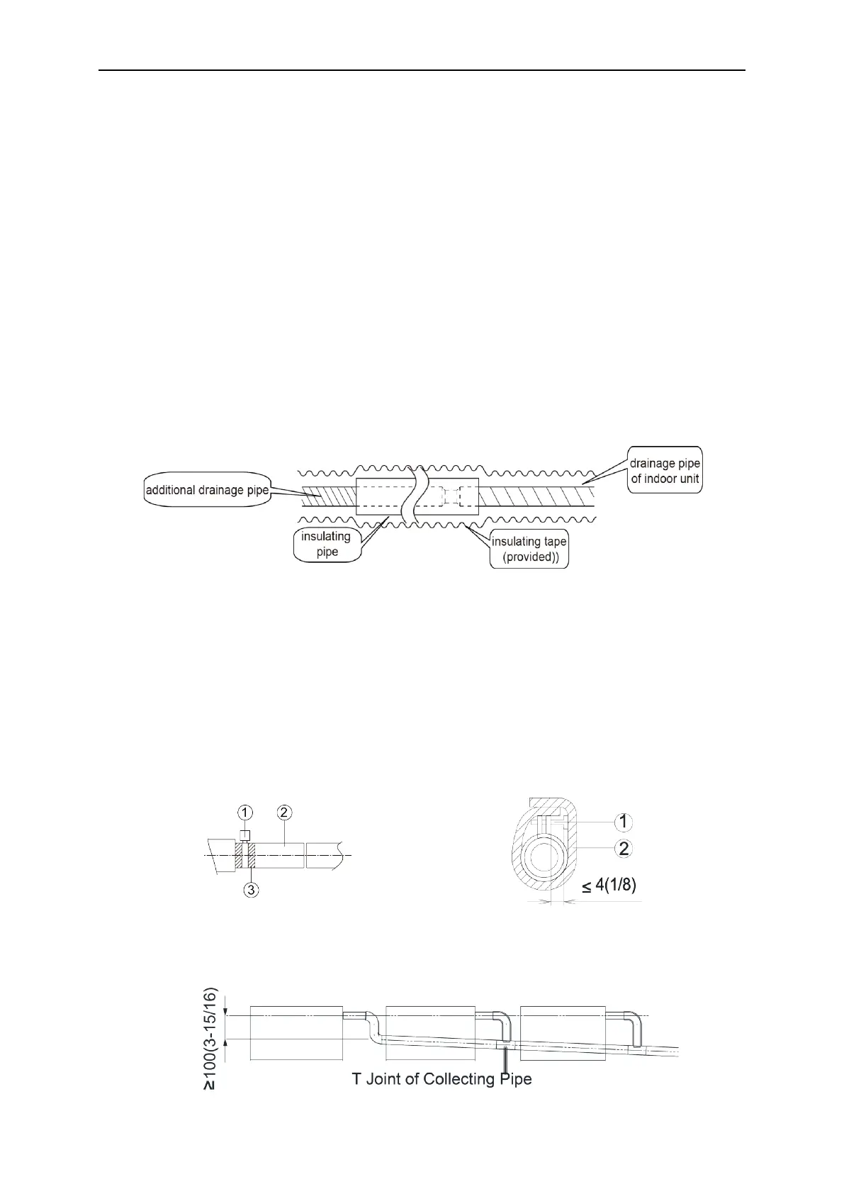
(5) When several unit's drain lines are connected, position the drain line about 100mm(4in.)
lower than the drainage port of each unit. Use heavier duty drain line if needed.
Fig 4.3.1
4.3.2 Drain Line installation
(1) Insert the drain hose into the drain hole and secure it with tape, as shown in Fig 4.3.2.
(2) Tighten the pipe clamp, with the distance between screw nut and hose smaller than
4mm(1/8in.).
① metal clamp(accessory)
② drain hose(accessory)
(3) Use sealing tape to insulate the pipe clamp and hose, see Fig.4.3.3.
① metal clamp(accessory)
②
thermal sponge(accessory)
Unit: mm(in.)
Fig 4.3.2 Fig 4.3.3
(4) When connecting several drain lines, follow the instruction as indicated in Fig 4.3.4.
Select the condensate drain line to match the unit capacity.
Unit: mm(in.)
Fig 4.3.4
 Loading...