GMV DC Inverter VRF
25
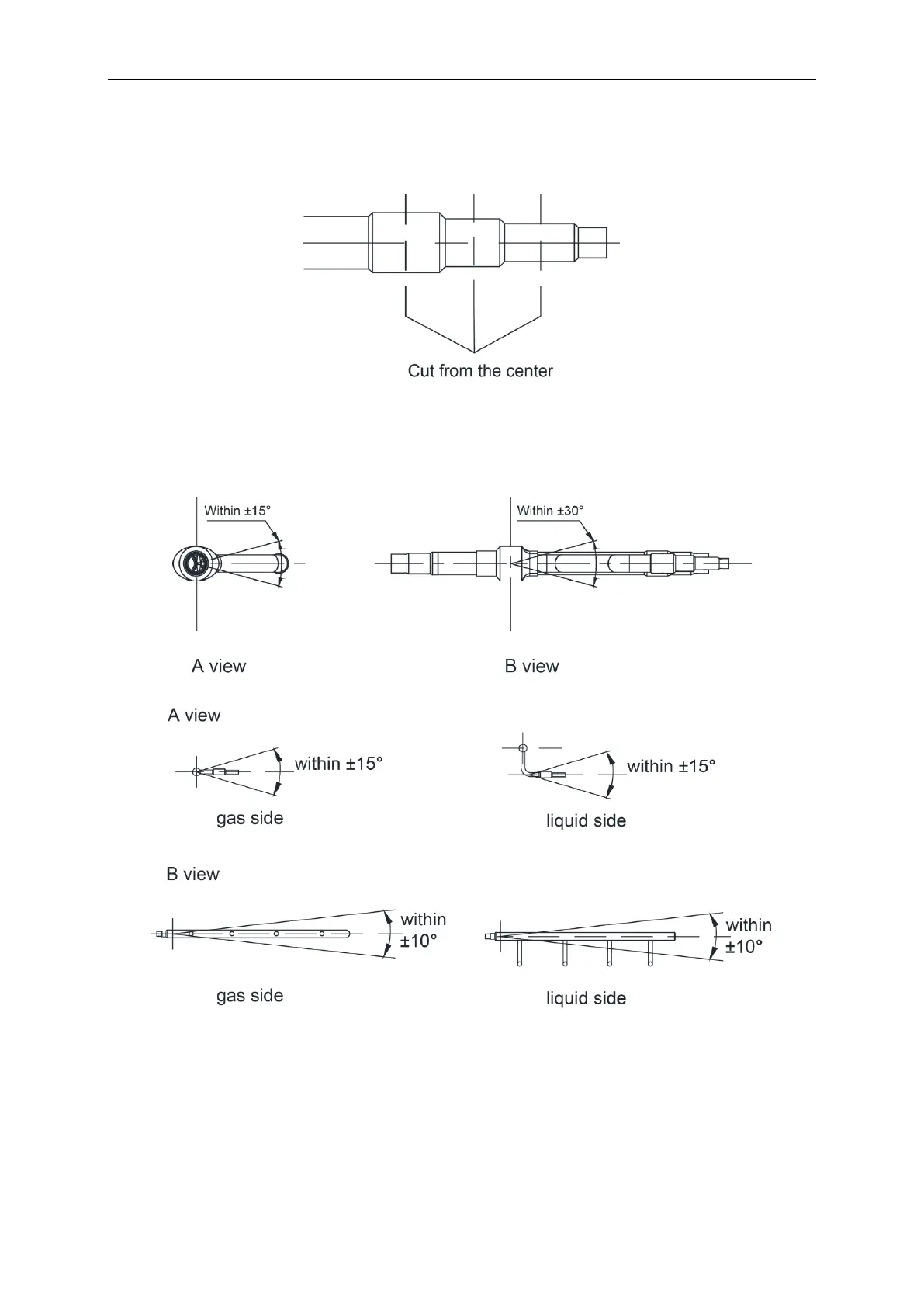
(2) Manifold has several pipe sections with different pipe size, which facilitates to match with
various copper pipe. Use pipe cutter to cut in the middle of the pipe section with different
pipe size and deburr as well. See Fig. 35.
Fig. 35
(3) Y-type manifold can be installed vertically or horizontally. Confirm the position and then
weld the manifold pipe. See the Fig. 36(a). T-type manifold must be installed horizontally
with inclination, see the Fig. 36(b).
Fig. 36(a)
Fig. 36(b)
(4) Manifold is isolated by insulating material that can bear 120
℃
(248
℉
)or higher
temperature. Manifold attached foam cannot be taken as insulating material.
4.4.3 Installation and thermal insulation for pipeline
(1) For multi VRF system, every copper pipe should be labeled so as to avoid
misconnection.
 Loading...
