Gree GMV6 DC Inverter VRF Units Service Manual
Note:
After the capability limit is set, the cooling or heating effect is correspondingly reduced.
Setting steps:
Step 1:
Enter n4 maximum output capability limit setting, and ensure that the master unit displays
as follows:
Function code Display status
Current
Display status Current status Display status
Step 2:
Press the SW1 up button and the SW2 down button to select the corresponding value.
Function code Display status
Current
Display status Current status Display status
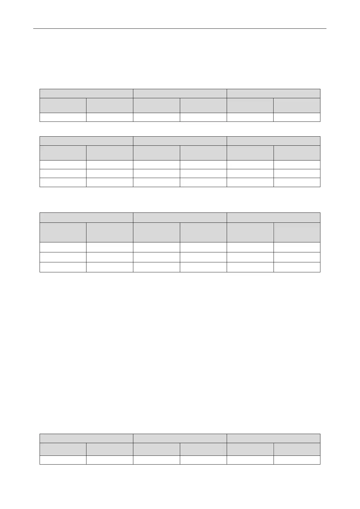
Step 3:
After selecting the value, press the SW3 confirm button. The master module displays as
follows:
LED1 LED2 LED3
Function code Display status
Current
process/mode
Display status Current status Display status
n4 On 10 On OC On
n4 On 09 On OC On
n4 On 08 On OC On
If you do not press any button on the master unit in 5 minutes, the system will automatically exit the
current screen and the unit will resume displaying the current status. (During setting, press SW4 to return
to the previous process. If the setting is completed, press SW4 to resume the unit to the current normal
working status.)
4.2.3.8 n5 Indoor Unit Engineering SN Offset
Introduction:
When different refrigerating systems are controlled in a centralized manner (by remote monitoring or
a centralized controller), this function sets the engineering numbers of indoor units and avoids their
conflict among different systems, and therefore must be set.
Set this function only in the master system, whose centralized control address SA2 is "0000×". For
details, see the settings in section "Address DIP Switch for Centralized Control (SA2_Addr-CC)".
Setting steps:
Step 1:
Enter n5 indoor unit engineering SN offset, and ensure that the master unit displays as
follows:
LED1 LED2 LED3
Function code Display status
Display status Current status Display status
n5 On 00 Blinks 00 Blinks
 Loading...

