Gree GMV6 DC Inverter VRF Units Service Manual
Step 2:
Press the SW3 confirm button to send the engineering number offset instruction. The master
module displays as follows:
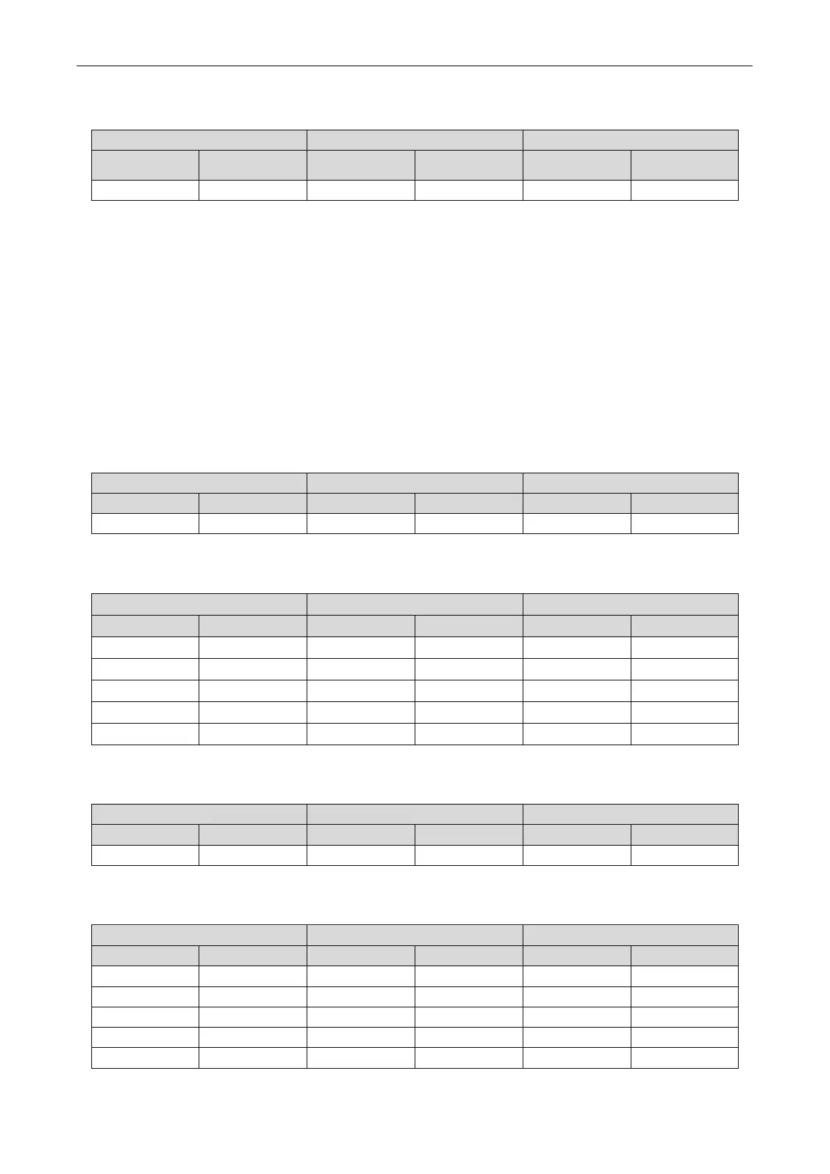
LED1 LED2 LED3
Function code Display status
Display status Current status Display status
n5 On 00 On OC On
After 10s, the system exits the mode and enters normal working.
4.2.3.9 IG Outdoor Unit Static Pressure
Each basic module can be set separately or uniformly by the master module.
When basic modules are set separately, the static pressure value of each module can be different;
when the modules are set uniformly, the static pressure value of each module remains the same. When
a static pressure value is set in either of the two modes, the previous mode setting limit is automatically
released.
The static pressure value of each basic module is subject to the last received set value.
Setting steps:
Enter the function setting. The master unit displays as follows:
LED1 LED2 LED3
Function code
Current process Display status Current status Display status
3P
01 Blinks OC Blinks
Press the SW1 up button and the SW2 down button to select the corresponding basic module: 00
means all modules, 01~-04 means module 1 to module 4.
1G On 01 Blinks OC Blinks
1G On 03 Blinks OC Blinks
After selecting the corresponding basic module, press the SW3 confirm button. The module displays
as follows. The current factory default status is 00.
Press the SW1 up button and the SW2 down button to select the corresponding static pressure mode
for the outdoor unit.
1G On ADD On 01 Blinks
After selecting the corresponding static pressure mode for the outdoor unit, press the SW3 confirm
 Loading...

