Gree GMV6 DC Inverter VRF Units Service Manual
LED1 LED2 LED3
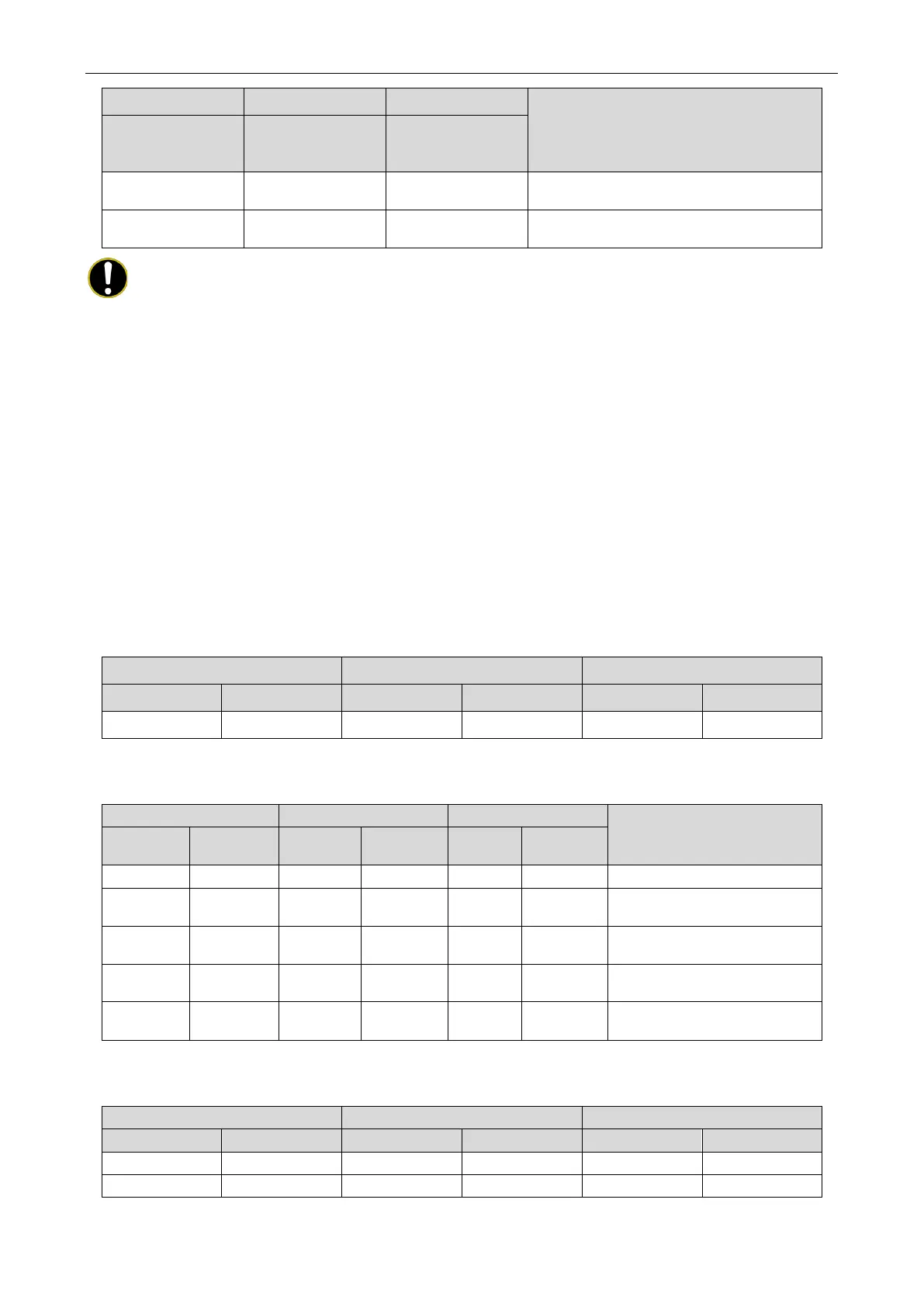
Description
Module address
Module
failure/indoor unit
Module status
ADD C9 ON
System running-fan emergency operation
ADD C9 OF
System standby-fan emergency operation
NOTES!
① This function is applicable only to dual-fan models;
② A module can set only one fan to emergency mode;
③ The default status is 00.
④ The system cannot run continuously for more than 120 hours in fan emergency operation
status. If it exceeds 120 hours, the entire system is stopped, and the indoor unit displays the
"Ad" limit operation code.
4.2.3.13 CA Module Failure Emergency Operation
This function is after-sales emergency setting when a module works abnormally. It shields the
abnormal module in a short time to ensure the emergency operation of other modules.
Setting steps:
Enter the function setting on the main board of the faulty basic module. The module displays as
follows:
LED1 LED2 LED3
Function code Display status Current process Display status Current status Display status
CA On 00 Blinks OC Blinks
Press the SW1 up button and the SW2 down button to select the corresponding module to enter and
exit emergency operation status.
Description
Function
Display
Current
Display
Current
Display
All basic modules run normally.
CA On 01 Blinks OC Blinks
The operation of module 1 is
CA On 02 Blinks OC Blinks
The operation of module 2 is
CA On 03 Blinks OC Blinks
The operation of module 3 is
CA On 04 Blinks OC Blinks
The operation of module 4 is
After selecting the corresponding value, press the SW3 confirm button. The shielded module displays
as follows:
 Loading...

