DC Inverter Multi VRF System
19
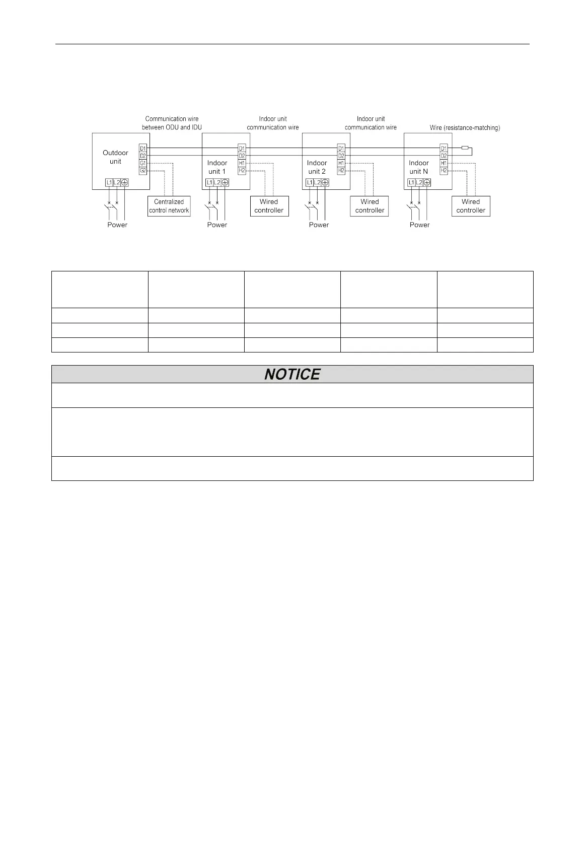
4.6.2 Wiring Diagram
(1) Connection of power cord and communication wire.
Separate power supply for IDU and ODU.
Fig.4.25
(2) Selection of air switch and power cord:
Model Power supply
Max Fuse
Size/Fusible Max.
Max Ckt, Bkr
Size/Disjoncteur
Min. Circuit Ampacity
(A)
GMV-48WL/C-T(U) 208/230V~ 60Hz 40 40 33
(1) Selection of circuit breaker and power cord in the above table is based upon unit’s maximum power (maximum
(2) Specification of power cord is based on the working condition where ambient temperature is 40°C(104°F) and
multi-core copper cable (working temperature is 90°C(194°F), e.g. power cable with YJV cross-linked copper,
insulated PE and PVC sheath) is lying on the surface of slot. If working condition changes, please adjust the
specification according to national standard.
(3) Specification of circuit breaker is based on the working condition where ambient temperature of circuit breaker is
40°C(104°F). If working condition changes, please adjust the specification according to national standard.
4.6.3 Engineering Wiring of Power Supply and Communication Cable
(1) Please refer Fig.4.26 & Fig.4.27 for engineering wiring. If there is the hole for cable tie in
wiring route, please fix the wire with cable tie. Connect the power cord and communication
cable to the corresponding terminal board and grounding screw according to the wiring
diagram.
(2) Please be noted that engineering wiring cannot touch the pipe and appliance.
(3) This figure is only applicable for engineering wiring reference of power supply and
communication cable. If there are differences between the figure structure and actual unit,
please refer to the actual unit.
(4) For engineering wiring, please refer to the wiring diagram provided with the unit.
 Loading...

