DC Inverter Multi VRF System
22
(9) Before test operation, make sure unit is power on and compressor has been preheated for
more than 8 hours. Touch the unit to check whether it’s normally preheated. If yes, start test
operation. Otherwise, compressor might be damaged.
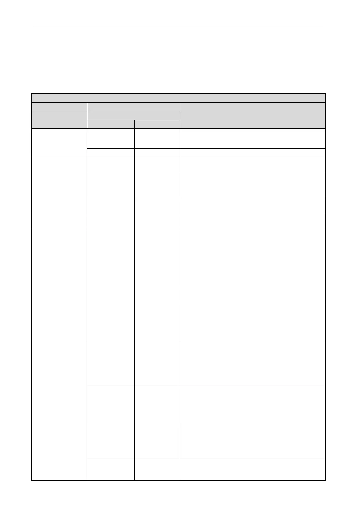
5.2.2 Test Operation and Debugging
Description of test operation procedures and main board display of ODU
Description of each stage of debugging progress
Code meaning and operation method
Progress
01_Set master unit
A0 ON
System is not debugged, hold main board’s SW3 button
for 5s to start debugging.
2s later, next step starts.
02_ Allocate
addresses
02/Ad
Display
System is allocating addresses. 10s later, dis
02/L7
Display
circularly
No master indoor unit. Display will be on for 1min, during
which master IDU can be set manually. If not, system will
set the unit with minimum IP address as the master IDU.
02/oC
Display
Allocation is finished. 2s later, next step starts.
03_ Confirm the
03/01
Display
System is confirming. 1s later, next step starts.
04_ Confirm the
quantity of IDU
04/00
~
16
Display
circularly
“00~16” displays the quantity of indoor unit. Confirm the
number manually. If the number is not consiste
display one, cut off power of IDU and ODU and check
whether communication wire of IDU is correctly
connected. After the check, connect power and start
debugging from progress 01. If the number is then
correct, press main board’s SW3 button to confirm. Then
04/oC
Display
System has confirmed the quantity. 2s later, next step
00
~
16/CL
Display
circularly
“00~16” displays the quantity of indoor unit identified by
the system. “CL” means the amount of indoor unit is very
little (amount of indoor unit<2), at this mome
buttons are invalid, the system cannot enter into the next
05_ Detect ODU’s
internal
communication and
capacity ratio
05/C2
Display
circularly
Communication between master ODU and driver has
error. Check the communication connection of ODU’s
main board and drive board. When the error is
eliminated,
start next step. If power is off during
troubleshooting, then restart debugging from progress 01
05/oC
Display
circularly
Communication of master ODU and driver is normal. Unit
will display as in the left for 2s and detect the capacity
ratio of IDU and ODU. If the ratio is within range, than
next step will start 2s later.
If the ratio is out of range, unit
05/CH
Display
circularly
Rated capacity ratio of IDU is too high. Chang
combination way of I
DU and ODU to make the ratio
within range. And restart debugging from progress 01.
05/CL
Display
circularly
Rated capacity ratio of IDU is too low. Change the
combination way of IDU and ODU to make the ratio
within range. And restart debugging from progress 01.
 Loading...

