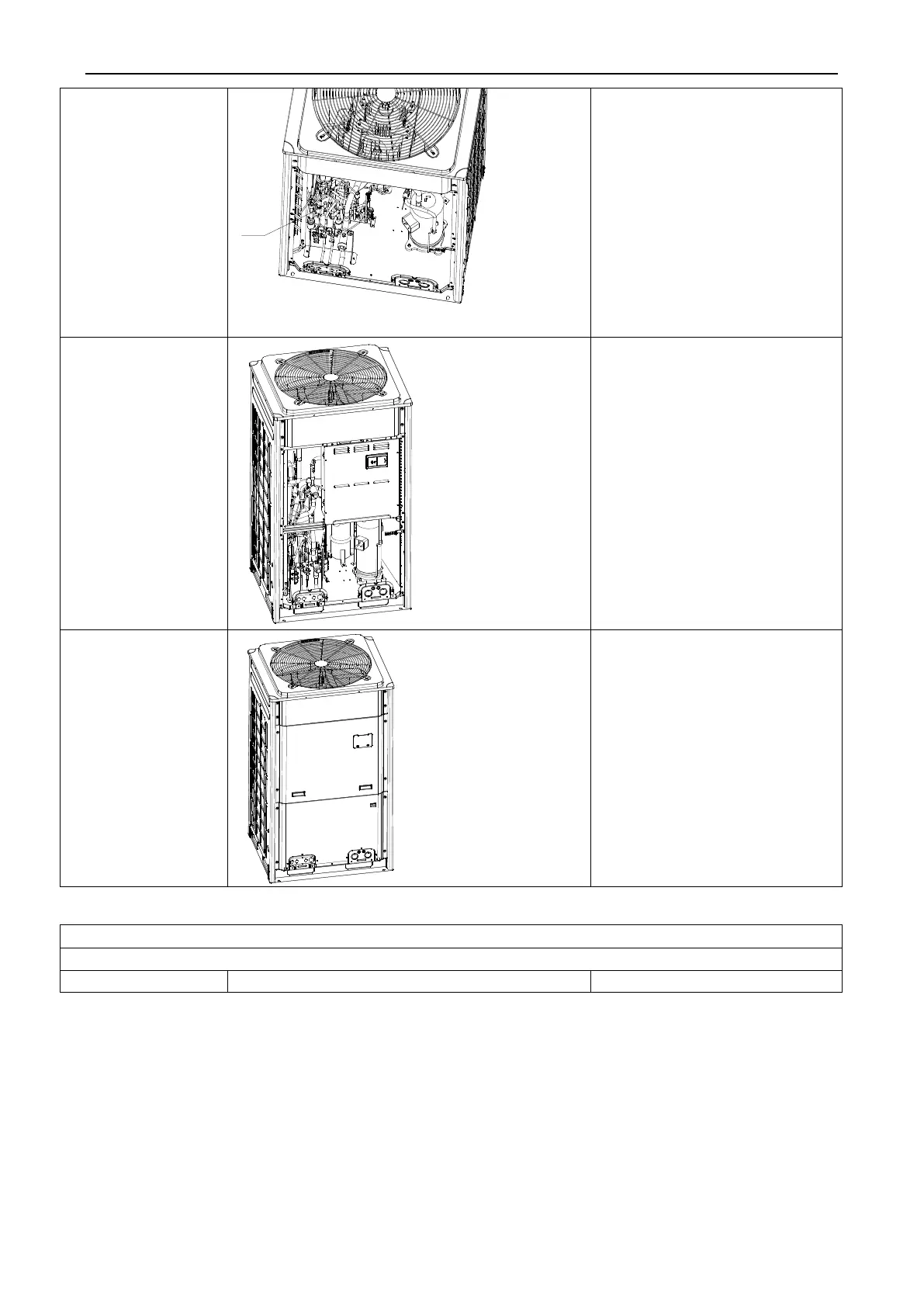
EasyManua.ls Logo

Gree GMV-615WM/B-X - Page 214

Gree GMV-615WM/B-X
375 pages
To Next Page IconTo Next Page
To Previous Page IconTo Previous Page
Loading...
GMV5 DC INVERTER VRF UNITS SERVICE MANUAL
211
5. Install a new
electric expansion
valve.
Weld the connecting pipes with
the electric expansion valve.
Before welding, cover the valve
with wet cloth.
●During welding, charge
nitrogen into the pipes. The
pressure should be controlled
within 0.5±0.1 kgf/cm2 (relative
pressure).
Note: Avoid nearby parts from
being burnt during welding.
Install the coil on the electric
expansion valve.
6. Fix and wire the
electric box.
●Put the electric box back to
original position and screw it.
Connect all lines.
7. Check and install
the front panels.
●Check various parts and
connecting lines.
If no problem is found, hook
the front panels and tighten the
screws.
Oil separator
Precondition: No refrigerant exists in the pipeline system and the power supply has been disconnected.
Step
Diagram
Operation Procedure

Table of Contents

Other manuals for Gree GMV-615WM/B-X

Related product manuals