GMV5 DC INVERTER VRF UNITS SERVICE MANUAL
240
3.2.3 LEDs and Interfaces
Power LED: a red LED. When it is on, it indicates that the converter is normally supplied with power;
when it is off, it indicates that the converter's power supply is abnormal.
Communication LEDs: two yellow LEDs. When a PC is delivering data, the data transmitting LED will
flash; when an air conditioning unit is uploading data to the PC, the data receiving LED will flash.
Function LEDs: three green LEDs:
If the RS485 to USB LED is steady on, it indicates that the converter is working in RS485 mode.
If the CAN to USB LED is steady on, it indicates that the converter is working in CAN mode.
If the HBS to USB LED is steady on, it indicates that the converter is working in HBS mode.
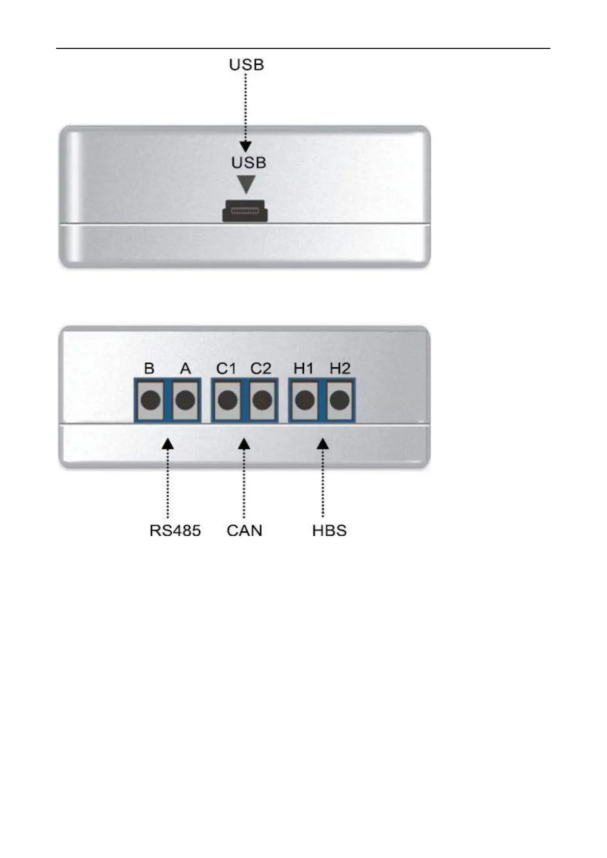
USB interface: connects to a USB data line.
CAN interface: When air conditioners work in CAN mode, they are connected to the converter over this
CAN interface. This interface is not distinguished by polarity. Thus, the two contacts C1 and C2 can be
used interchangeably.
HBS interface: When air conditioners work in HBS mode, they are connected to the converter over this
HBS interface. This interface is not distinguished by polarity. At present, Gree Debugger and monitor
software do not support this interface.
 Loading...


