GMV5 DC INVERTER VRF UNITS SERVICE MANUAL
4
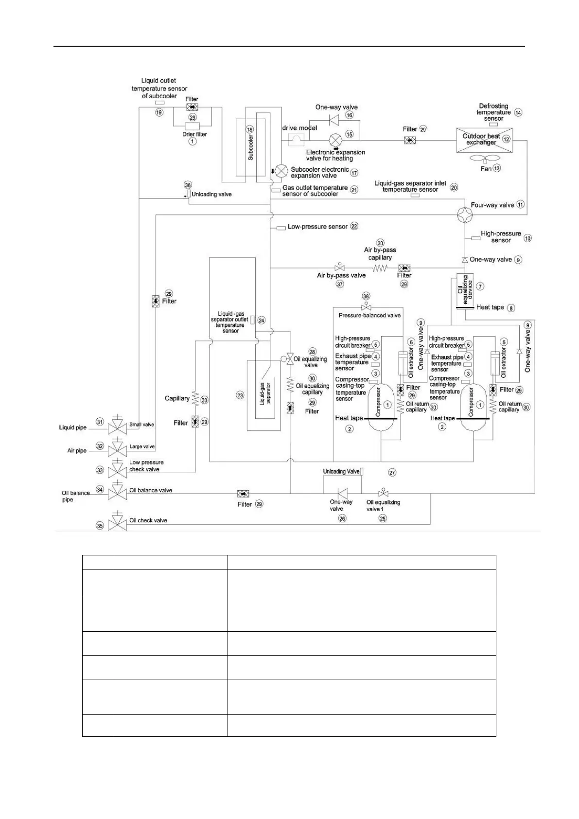
3. Piping Diagram of GMV-504WM/B-X, GMV-560WM/B-X and GMV-615WM/B-X
4. Names and Main Functions of Components
Adjusts its own rotational speed based on the actual requirement
of the system to implement capacity control.
Maintains a proper oil temperature in the compressor when the
compressor is in standby status, ensuring the reliability during
compressor startup.
Compressor casing-top
temperature sensor
Detects a compressor's exhaust gas temperature for compressor
control and protection.
Exhaust pipe temperature
sensor of compressor
Detects a compressor's exhaust gas temperature for compressor
control and protection.
High-pressure circuit
breaker
Protects a compressor by sending feedback signal to stop the
system when the compressor's discharge temperature exceeds the
operating value of high-pressure circuit breaker.
Separates the gas and oil in the system to ensure compressor
reliability.
 Loading...

