GMV5 DC INVERTER VRF UNITS SERVICE MANUAL
77
m=(m1-m2)+(m3-m4)+…+(mn-1-mn)
Quantity of refrigerant to be perfused during running m`=M-m
M is the required total quantity
If the pre-perfusion quantity (m) reaches the required total quantity for the system, turn off the valve of
the refrigerant tank immediately to finish perfusing and proceed with step 11.
Step 11: Remove the pressure gauge.
2. Refrigerant Perfusion During Running
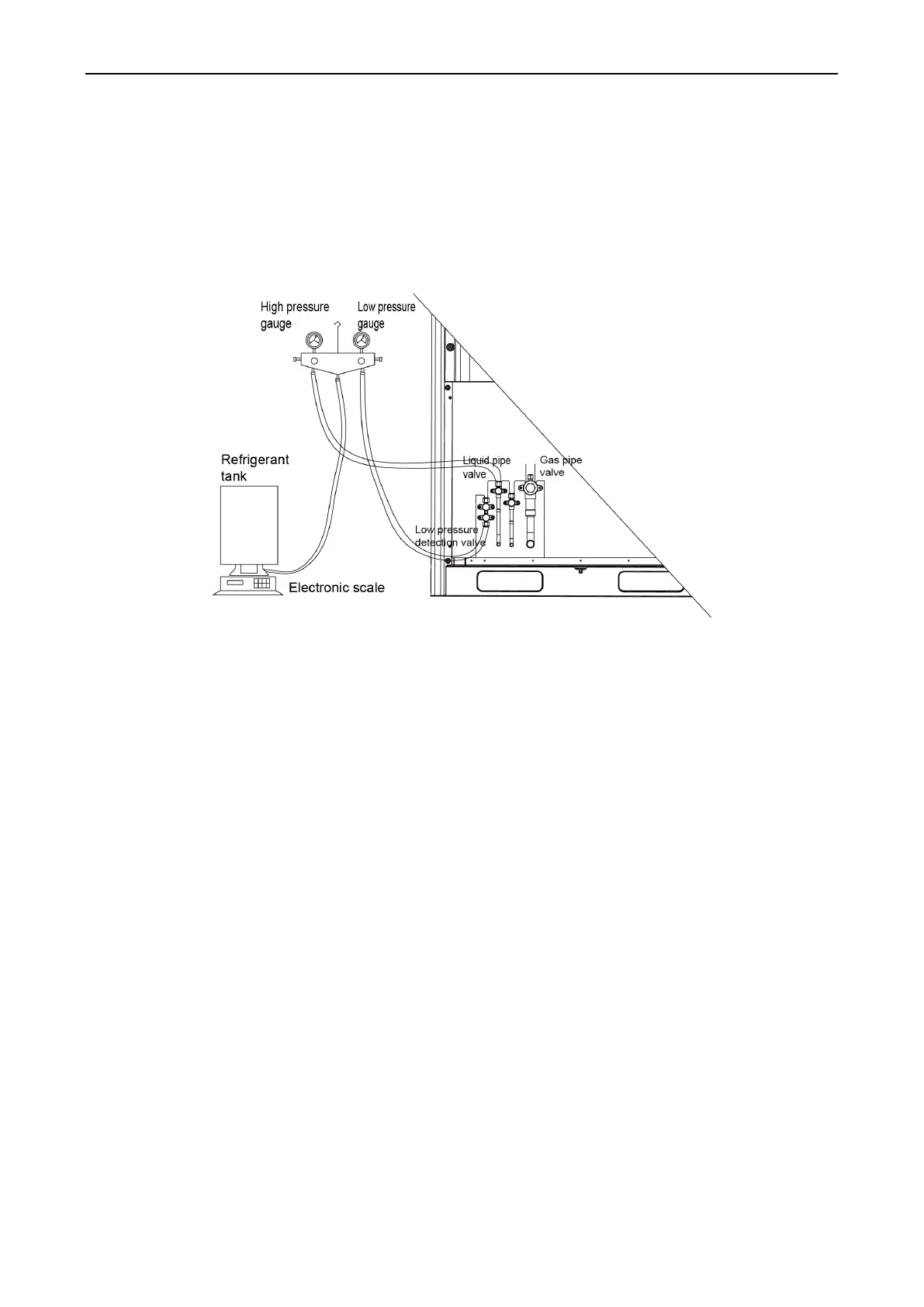
Step 1: Turn off the valve of the refrigerant tank and reconnect the pressure gauge pipe. Disconnect the
low pressure gauge pipe from the detection valve opening of the gas liquid and connect it to the
low pressure detection valve, as shown in the following figure.
Step 2: Turn on the valves for the liquid and gas pipes of each module completely. For the modular unit,
the oil-equalizing valve of each module also needs to be turned on.
Step 3: Make the system to run in commissioning mode via the commissioning software or the main
board of the ODU. (For details, see the description on commissioning.)
Step 4: When the commissioning step goes to refrigerant perfusion, turn on the valve of the refrigerant
tank and perfuse the remaining quantity (m`).
Step 5: After all refrigerant is perfused, turn off valve of the refrigerant tank and wait till commissioning is
automatically is completed for the system.
Step 6: Remove the pressure gauge to finish refrigerant perfusion.
 Loading...

