Gree GMV6 DC Inverter VRF Units Service Manual
Checklist Before GMV6 Commissioning
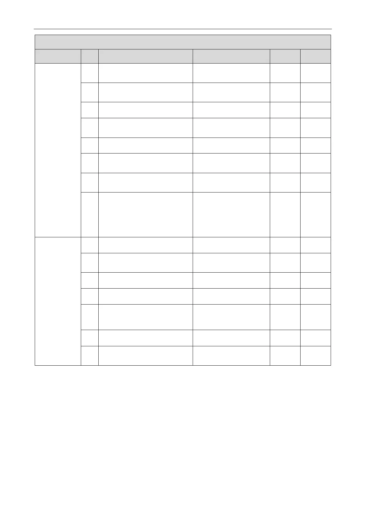
Category No. Item Reference Value Qualified Inspector
Communication
system
30
Does the communication cable
material meet the unit design
—
31
Is the communication connection
between outdoor unit modules
—
32
Is the DIP switch of the master unit
of the outdoor unit module correct?
—
33
Is the communication between the
outdoor master unit and the indoor
Serial connection
34
Is the communication connection
between indoor units correct?
—
35
Is the communication connection
between the indoor unit and the
wired controller correct?
—
36
Is the last communication indoor
unit installed with a communication
—
37
The communication cable cannot
be laid in the same trough as the
power cable. It is laid separately in
a flame-retardant hard PVC pipe.
The parallel spacing between a
communication cable and a strong-
current cable is greater than 20 cm.
—
Indoor unit
installation
38
Does the indoor unit drain pipe
have a slope of 1/100?
—
39
Does the height of the indoor unit
riser drain pipe meet the
—
40
Does the indoor unit drain
smoothly?
—
41
Is there a U-shaped trap for indoor
unit drainage?
—
42
Is there a soft joint at the air outlet
and air return vent of the indoor
unit? Does the return air have a
—
43
Does the indoor unit water pipe
have an emptying port?
—
44
Is a "main" label attached to the
wired controller or panel of the
—
3.2 Debugging and Operation
3.2.1 Precautions
(1) Do set one (only one) module as the main module during debugging.
(2) When there is no special requirement, the other functions do not need to be set, and it can be
operated according to the factory settings. For special functions, please refer to the related
technical documents.
(3) Installation and debugging operation must comply with the relevant regulations of the local country
or region.
 Loading...