141
GMV5 HR HEAT RECOVERY
VRF Units Technical Sales Guide
(2) All communication wires of GMV5 are connected by screws.
wiring screw
terminal board
Fig.36
(3) If a single communication wire is not long enough and needs to be connected, the connected joint
must be welded or pressure-welded. Do not simply twist the wires together.
11.3 Connection Method and Procedure of Communication Cable
11.3.1 Communication connection between the indoor unit and outdoor unit
The indoor unit is connected to the outdoor unit through the D1/D2 port of the terminal plate XT2. The
figures below show the connection method of the single outdoor unit and connection method of the
modular outdoor unit.
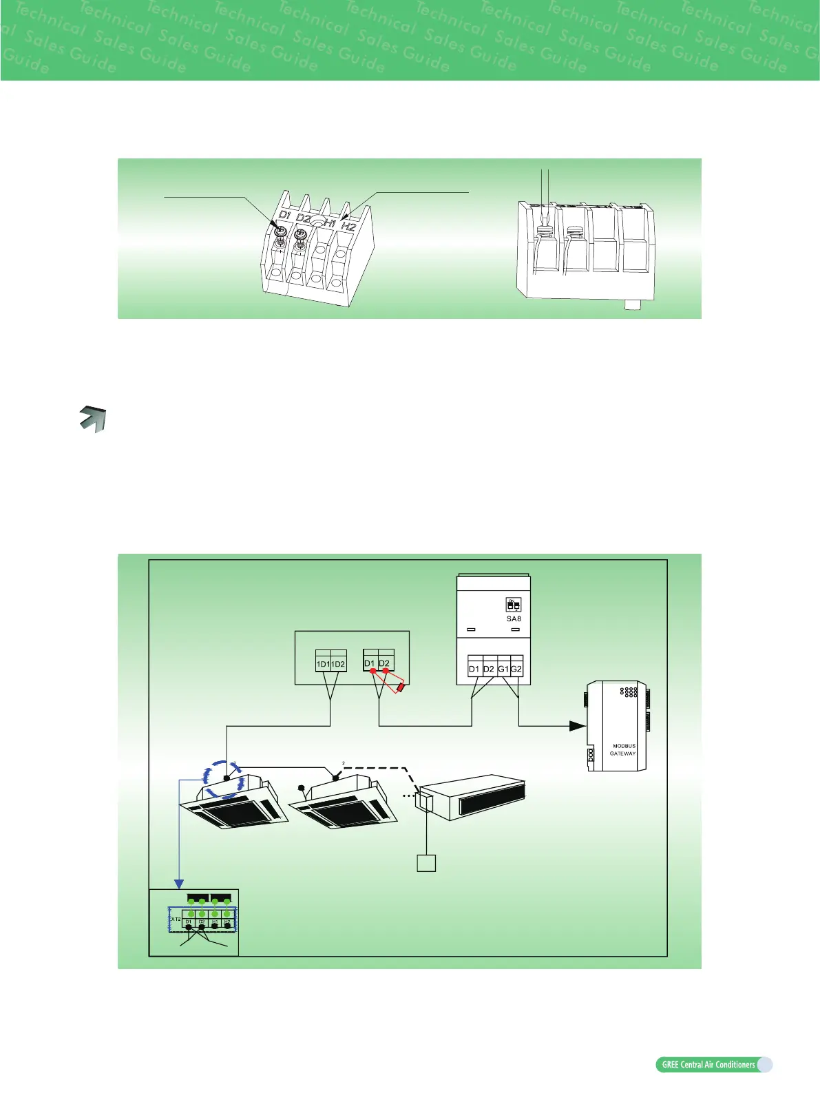
Communication connection mode of the single module system
Outdoor unit (master module)
Mode
exchanger
Communication connection between indoor units
MODBUS or
BACnet gateway
control is required)
Connect
outdoor unit
Next indoor unit
Indoor unit
Indoor unit NO.1 Indoor unit NO.2
Indoor unit
NO.n(8max)
matched resistance
Communication
Wired controller

 Loading...


