145
GMV5 HR HEAT RECOVERY
VRF Units Technical Sales Guide
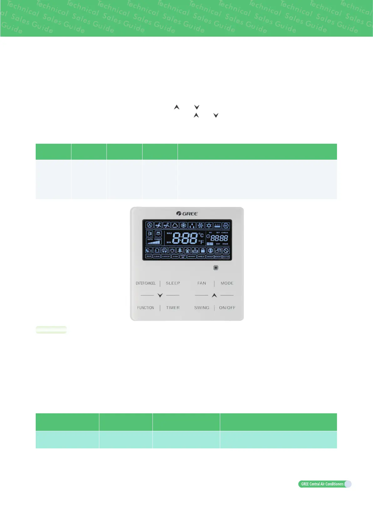
(1) The slave wired controller can be set in the power-on or power-off status:
(2) Press and hold the “FUNCTION” button on the wired controller to be set to a slave wired controller for
five seconds. The temperature area displays “C00”. Continue holding the “FUNCTION” button for five
seconds to enter the wired controller parameter setting interface. The temperature area displays “P00”
by default.
(3) Select a P13 parameter code by pressing
“ ” or “ ”
. Press the “MODE” button to switch to parameter
value settings. The parameter value blinks. Press
“ ” or “ ”
to select “02”, and then press the “ENTER/
CANCEL” button to complete settings.
(4) Press the “ENTER/CANCEL” button to return to the upper-level menu till quitting parameter settings.
The user parameter setting list is as follows:
Parameter
Code
Parameter
Name
Parameter
Range
Default Value Remarks
P13
Wired
controller
address
settings
01: master
wired
controller
02: slave wired
controller
01
When two wired controllers simultaneously control one or more indoor
units, the two wired controllers must use different addresses. The
slave wired controller (address: 02) does not have the unit parameter
setting function except its own address settings.
NOTES:
a. The default factory setting of all the wired controllers is the master wired controller status.
b. In the parameter setting status, the “FAN”, “Timer”, “SLEEP”, and “SWING” buttons are invalid. By
pressing “ON/OFF”, you can return to the main interface but will not power on/off the unit.
c. In the parameter setting status, signals of the remote controller are invalid.
11.3.3 Connection mode between the air duct-type indoor unit and receiving LED panel
When the air duct-type indoor unit needs to be connected to a remote receiving LED panel, they are
connected through DISP 1 and DISP 2 of the main board for indoor unit:
Indoor Unit Type
Model of Remote
Receiving LED Panel
Connection Wire Type Main Board Interface of Corresponding Indoor Unit
Air duct-type indoor unit JS05
Inter-board connecting line
(17 cores)
DISP1 (interconnected to the 8-core interface)
DISP2 (interconnected to the 9-core interface)

 Loading...


