Gree GMV6 DC Inverter VRF Units Service Manual
213
4.1.1 Mechanical Inspection
(1) Confirm that the unit power is disconnected.
(2) Remove the electrical appliance cover.
(3) Check whether the power cable is fixed on the wiring board.
(4) Check whether the fuses on the main board and filter board are damaged.
(5) Check whether the varistors on the main board and filter board are damaged.
4.1.2 Electrical Inspection
Check the power cable from the main switch board to the ODU:
(1) Use an ohmmeter of at least 500V DC to check whether the insulation resistance between each
phase and the ground reaches at least 1 megohm. Small insulation resistance indicates a
potential electric leakage.
Warning:
Electric shock
(2) After the checking, connect the power and verify that the voltage of the power terminals is correct:
The power voltage between two phases is 460VAC±10%.
The unbalance rate of the power between two phases does not exceed 2%.
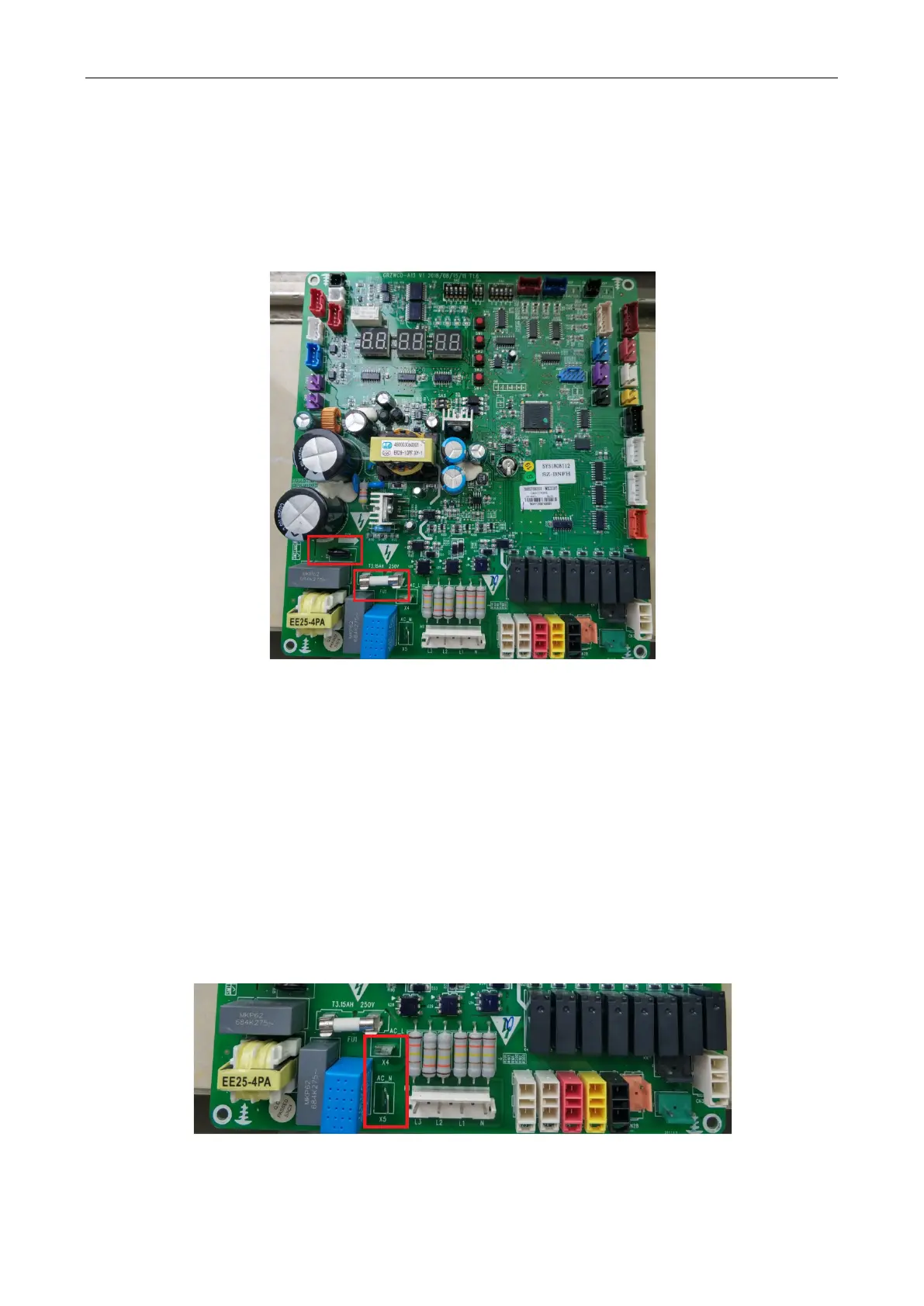
(3) Check the power on the main control board:
Confirm that the X4 and X5 on the main control board are active.

 Loading...

