Gree GMV6 DC Inverter VRF Units Service Manual
256
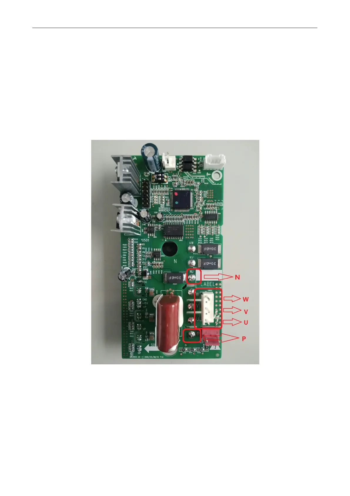
(1) Before the inspection: Find a correct digital multimeter and switch it to the diode gear. Power off the
unit and wait two minutes. Disconnect the U, V and W cables of the fans from the drive board. Do
not operate without waiting two minutes after the unit is powered off.
(2) Testing method: Point the black probe of the multimeter to the P bonding pad shown in the following
figure and the red probe to U, V and W wiring terminals respectively and check the readings of the
multimeter; point the red probe of the multimeter to the N bonding pad shown in the following figure
and the black probe to U, V and W wiring terminal respectively and check the readings of the
multimeter.
(3) Result analysis: If all the readings of the multimeter are between 0.3 V and 0.7 V in the above six
conditions, the module is normal; if any of the readings is 0, the module is damaged.
4.9 Main Board
The main board is used to control the load of the ODU.

 Loading...

