Gree GMV6 DC Inverter VRF Units Service Manual
325
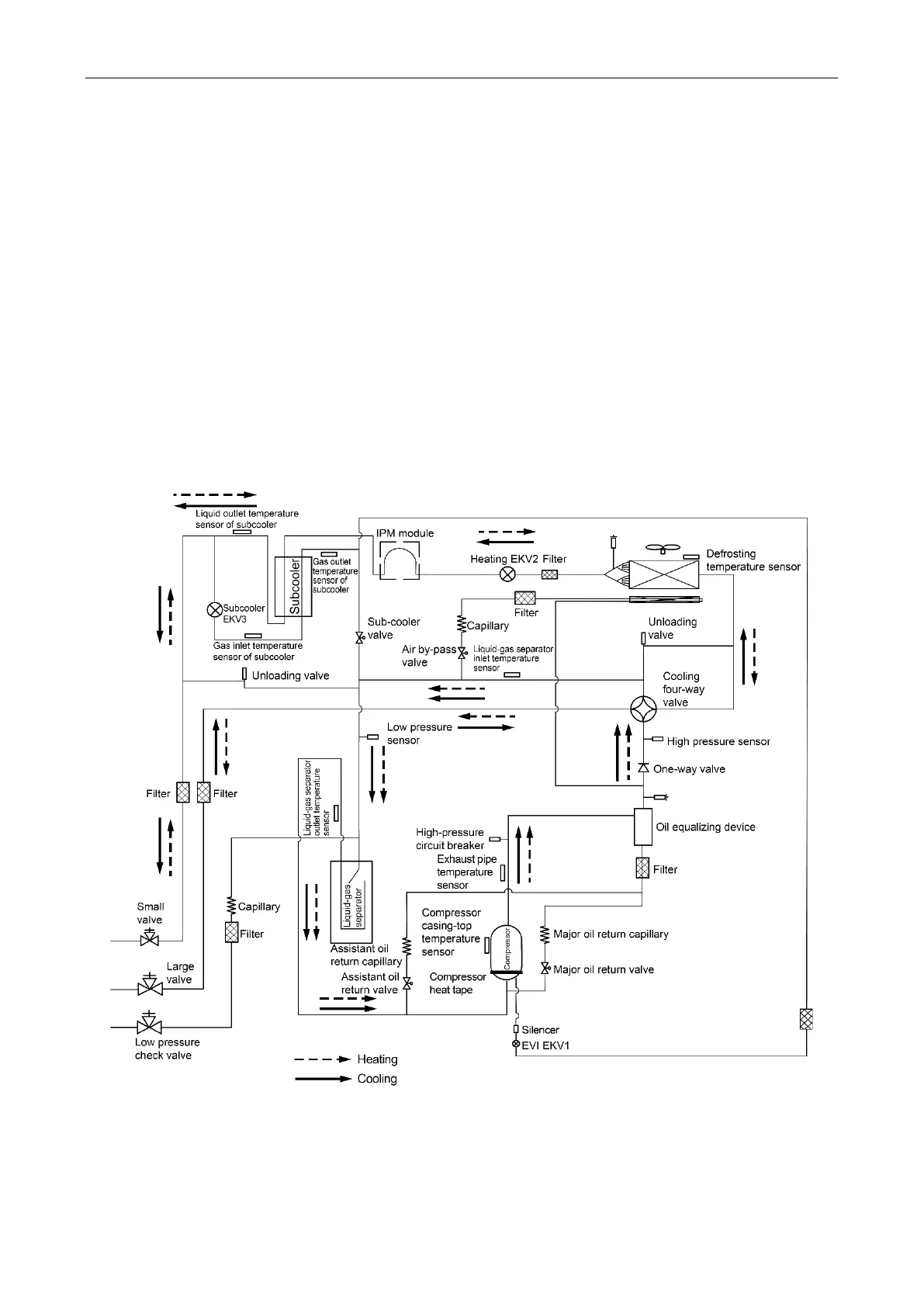
Appendix 6 Schematic Diagram
The outdoor unit of GMV6 multi VRF unit can be realized by parallel combination of modules, and
the indoor unit can also be composed of multiple units in parallel. The working principle is as follows:
when the indoor unit is running in the cooling mode, the outdoor unit starts the outdoor module according
to the running load demand of the indoor unit. The outdoor heat exchanger is used as the condenser of
the system, and the heat exchangers of indoor units are connected in parallel as the evaporator of system.
It realizes the adjustment of the air temperature and humidity for indoor space through the return air
circulation of the indoor unit; when the indoor unit is in the heating mode, all the four-way valves of the
outdoor unit module are switched to the energizing state, the outdoor heat exchanger is used as the
evaporator of the system and the heat exchanger of indoor unit is used as the condenser of the system.
The air temperature and humidity in the indoor space is realized by the return air circulation of the indoor
unit.
Working principle diagrams:
System principle diagram of GMV-224WM/G-U, GMV-280WM/G-U and GMV-335WM/G-U

 Loading...

