118
8.3 Piping selection
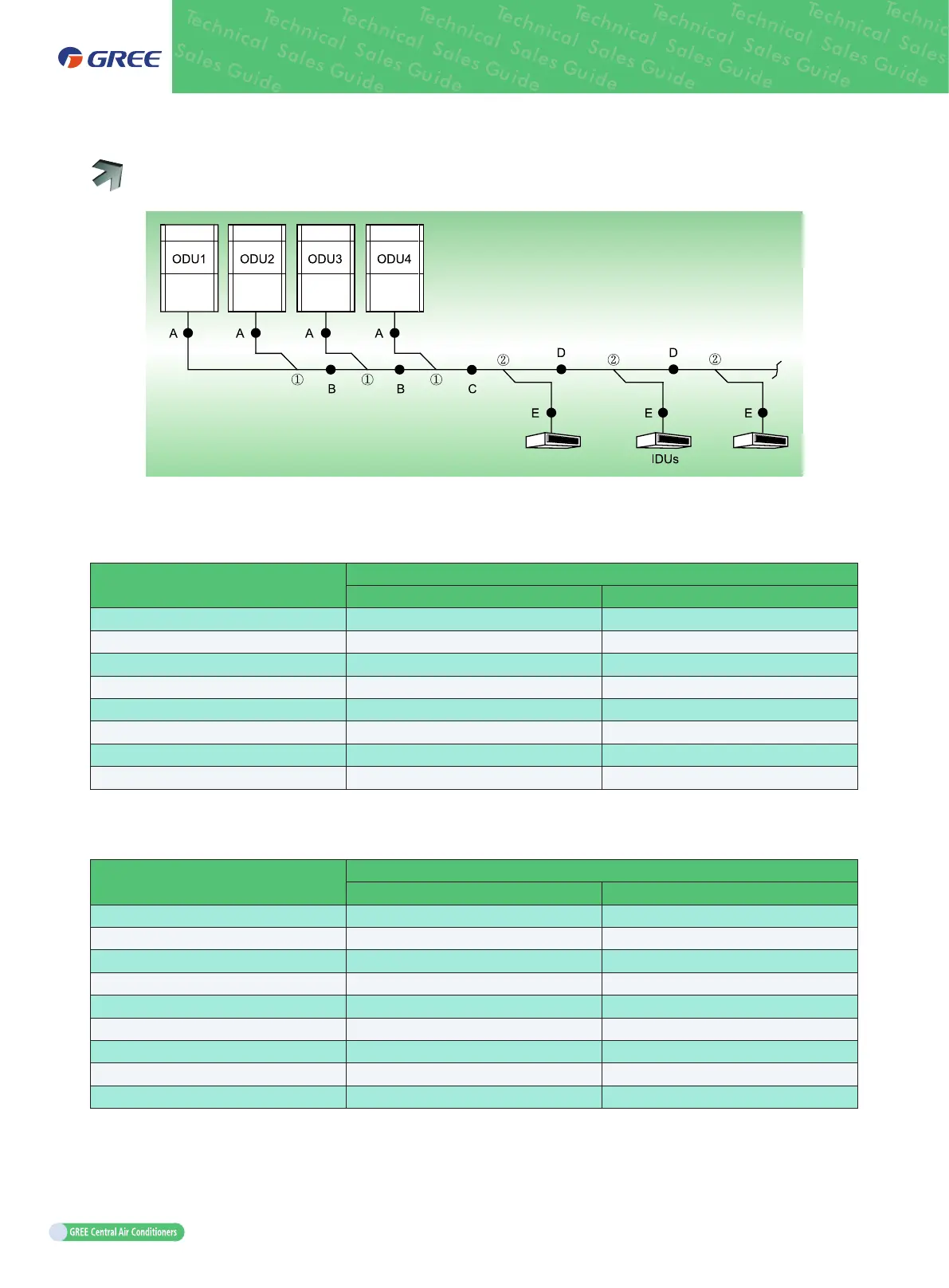
(1) When its modular units connection, the ODU must be installed in capacity order: ODU 4≥ODU
3≥ODU 2≥ODU 1.
(2) Pipe "A" between the outdoor unit and the manifold of outdoor unit.
The pipe size is based on the capacity of upstream module.
Basic module (single module system)
Piping size between the rst branch of ODU and IDU
Gas pipe (mm) Liquid pipe (mm)
GMV-224WM/H-X
Φ
19.05
Φ
9.52
GMV-280WM/H-X
Φ
22.2
Φ
9.52
GMV-335WM/H-X
Φ
25.4
Φ
12.7
GMV-400WM/H-X
Φ
25.4
Φ
12.7
GMV-450WM/H-X
Φ
28.6
Φ
12.7
GMV-504WM/H-X
Φ
28.6
Φ
15.9
GMV-560WM/H-X
Φ
28.6
Φ
15.9
GMV-615WM/H-X
Φ
28.6
Φ
15.9
(3) Fitting pipe "B" between outdoor unit manifold; fitting pipe "C" from outdoor unit to indoor manifold.
Pipe size (between two manifolds from basic modules) is based on the total capacity of upstream
modules.
Total rated capacity of upstream module
Q (kW)
Piping size among ODU modular branches
Gas pipe (mm) Liquid pipe (mm)
Q≤22.4
Φ
19.05
Φ
9.52
22.4<Q≤30.0
Φ
22.2
Φ
9.52
30.0<Q≤40.0
Φ
25.4
Φ
12.7
40.0<Q≤45.0
Φ
28.6
Φ
12.7
45.0<Q≤68.0
Φ
28.6
Φ
15.9
68.0<Q≤96.0
Φ
31.8
Φ
19.05
96.0<Q≤135.0
Φ
38.1
Φ
19.05
135.0<Q≤186.0
Φ
41.3
Φ
19.05
186.0<Q
Φ
44.5
Φ
22.2
(4) Fitting pipe "D" between indoor side manifolds.
Pipe size (between two manifolds at indoor unit side) is based on the total capacity of downstream
indoor unit(s).

 Loading...

