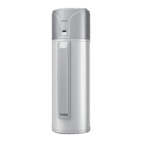
Air Source Heat Pump Water Heater
18
Fig. 3-4 Installation Diagram of Wired Controller
Fig. 3-3 is the installation diagram of wired controller. Cut off power supply of
heavy-current wire embedded in mounting hole in the wall before installation. The
installation method is as below:
Pry the removal port with straight screwdriver to separate the front panel and
soleplate of wired controller;
Pull out the communication cable(4-core twisted pair wire) in the base box and
then make the communication cable go through the hole of soleplate of wired
controller;
Joint the controller’s soleplate and base box with screws M4×25;
Insert the communication cable(4-core twisted pair wire) into controller’s slot;
Buckle the front panel and soleplate of controller together.
Caution
During the following connections, pay special attentions to prevent malfunction
due to electromagnetic interference:
(1) The communications line of the wired controller and the line of the

 Loading...