80DWFK6HULHV'&
,QYHUWHU6HUYLFH0DQXDO
45
DPOUSPM
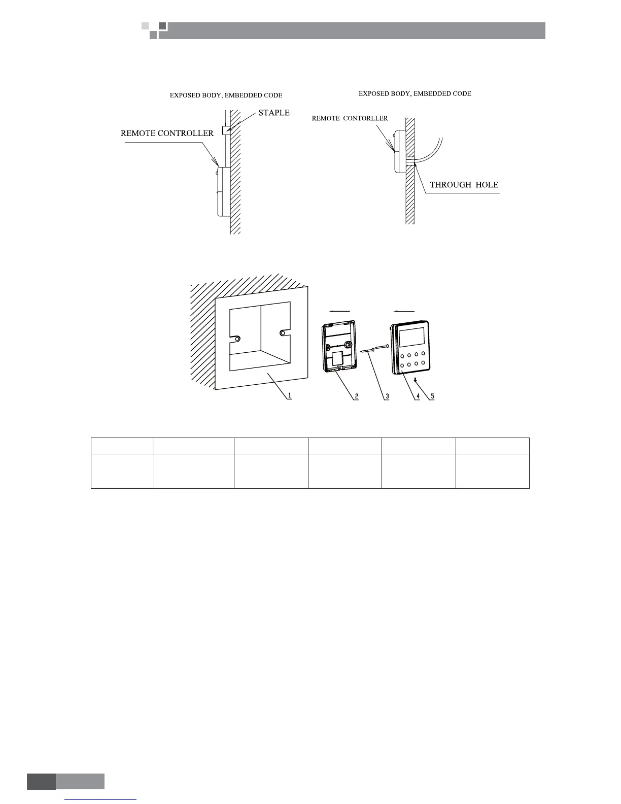
3.3 Installation of Wired Controller and Project Debugging
3.3.1 Installation of Wired Controller
Fig.3.3.1: Fig.1 Surface mounting of Cable Fig.3.3.2: Fig.2 Concealed mounting of Cable
Fig.3.3.3: Sketch for Installation of Wired Controller
No. 1 2 3 4 5
Description
Socket’s base
box installed in
thewall
Soleplate of
controller
Screw M4×12
Front panel of
controller
Screw ST2.9×6
Fig.3.3.3: Sketch for Installation of Wired Controller. Pay attention to the following items during installation
of wired controller:
1. Cut off power supply of heavy-current wire embedded in mounting hole in the wall before installation. It
is prohibited to perform the whole procedure with electricity.
2. Pull out 4-core twisted pair line in mounting hole and then make it through the rectangle hole at the back
of controller’s soleplate.
-RLQWWKHFRQWUROOHU¶VVROHSODWHRQZDOOIDFHDQGWKHQ¿[LWLQPRXQWLQJKROHZLWKVFUHZV0
×
12.
4. Insert the 4-core twisted pair line through rectangle hole into controller’s slot and buckle the front panel
and soleplate of controller together.
$WODVW¿[WKHFRQWUROOHU¶VIURQWSDQHODQGVROHSODWHZLWKVFUHZV67
2.9×6
.
Caution:
During connection of wirings, pay special attention to the following items to avoid interference of
electromagnetism to unit and even failure of it.
1. To ensure normal communication of the unit, signal line and wiring (communication) of wired controller
should be separate from power cord and indoor/outdoor connection lines. The distance between them should
be kept 20cm in min.
2. If the unit is installed at the place where there is interference of electromagnetism, signal line and wiring
(communication) of wired controller must be shielded by twisted pair lines.
 Loading...