Service Manual
36
Installation and Maintenance
1.Pay attention to dust prevention and take relevant
safety measures when opening the
hole.
2.The plastic expansion particles are not provided and
should be bought locally.
Note:
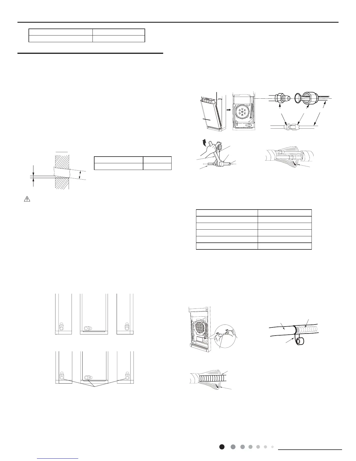
Step three: outlet pipe
1. The pipe can be led out in the direction of left, right or rear.
(As show in Fig.2)
2. After confirming the direction of outlet pipe, loosen the
screws at the upper and lower adjusting baffle to let the
connection pipe/drain pipe connects the indoor unit. (As show
in Fig.3)
Fig.2
Fig.3
upper and lower adjusting baffle
left back
right
pipe
union nut
union nutpipe joint
pipe
Step four: connect the pipe of indoor unit
1. Take out the left and right screw cover and then remove
the screws on air-inlet panel to remove the panel.(As show in
Fig.4)
2. Aim the pipe joint at the corresponding bellmouth.(As show
in Fig.5)
Refer to the following table for wrench moment of force
:
Fig.5
Fig.6
Fig.4
Fig.7
Step ve: install drain hose
1. Connect the drain hose to the outlet pipe of indoor unit.(As
show in Fig.8)
2. Bind the joint with tape.(As show in Fig.8)
3. Add insulating pipe in the indoor drain hose in order to
prevent condensation.(As show in Fig.10)
Fig.10
drain hose
insulating pipe
Fig.8
Fig.9
.
Step six: connect wire of indoor unit
1. Make the power connection wire go through the cable-
cross hole of indoor unit(As show in Fig.11)
3. Pretightening the union nut with hand.
4. Adjust the torque force by referring to the following sheet.
Place the open-end wrench on the pipe joint and place the
torque wrench on the union nut. Tighten the union nut with
torque wrench.(As show in Fig.6)
5. Wrap the indoor pipe and joint of connection pipe with
insulating pipe, and then wrap it with tape. (As show in Fig.7)
Φ70mm
8.5 Installation of Indoor Unit
Model Piping hole
All models Φ70mm
Step one: choosing installation Iocation
Recommend the installation location to the client and then
conrm it with the client.
Step two: open piping hole
1.Choose the position of piping hole according to the direction
of outlet pipe.
2.Open a piping hole with the diameter of Φ70mm on the
selected outlet pipe position. In order to drain smoothly, slant
the piping hole on the wall slightly downward to the outdoor
side with the gradient of 5-10°. (As show in Fig.1)
Fig.1
Model Capacity of air switch
24/48/55K 25A
Hex nut diameter(mm) Tightening torque(N
.
m)
Φ6 15~20
Φ9.52 30~40
Φ12 45~55
Φ16 60~65
Φ19 70~75
 Loading...