Do you have a question about the Gree GVA24AL-K3NNC7A/I and is the answer not in the manual?
Lists indoor, outdoor units, and remote controller models.
Comprehensive technical specs for GVA24AL, GVA48AL, GVA55AL models.
Graphical performance data vs. outdoor temperature for cooling and heating.
Charts showing indoor noise levels at various fan speeds for different models.
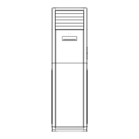
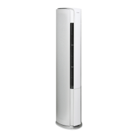
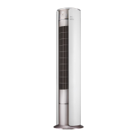
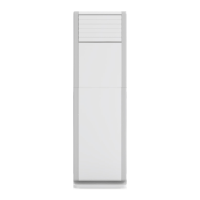
Visual representation and measurements for the indoor unit.
Visual representation and measurements for the outdoor units (24K, 48/55K).
Wiring schematics and symbol explanations for indoor and outdoor units.
Shows top and bottom views of printed circuit boards with component labels.
Explains buttons on the unit and their corresponding display icons.
Details remote controller buttons, icons, and operational notes.
Explains operation conditions for Auto, Cooling, Drying, Heating, and Fan modes.
Essential safety guidelines for installation, relocation, and unit maintenance.
Outlines general steps for unit installation, including dimension requirements.
Parts checklist, location selection, and electrical connection requirements.
Procedure for evacuating the system and checking for refrigerant leaks.
Checklist for verifying installation and performing initial operation tests.
List of error codes, their meanings, causes, and solutions.
Diagnostic guides for common malfunctions and protection modes.
Solutions for typical operational issues like starting problems, cooling/heating failures, and sounds.
Exploded views and part numbers for the indoor unit.
Exploded views and part numbers for the outdoor units.
Detailed steps for safely removing components from the indoor unit.
Detailed steps for safely removing components from the outdoor unit.
Reference for converting between Celsius and Fahrenheit temperatures.
Information on pipe lengths, refrigerant oil, and charging amounts.
Proper procedures for expanding refrigerant pipes to ensure leak prevention.
Lists resistance values for temperature sensors at various temperatures.
| Cooling Capacity | 24000 BTU/h |
|---|---|
| Heating Capacity | 24000 BTU/h |
| Refrigerant | R410A |
| Energy Efficiency Ratio (EER) | 3.21 |
| Power Supply | 220-240V/50Hz/1Ph |
| Noise Level (Indoor Unit) | 45 dB(A) |
| Noise Level (Outdoor Unit) | 55 dB(A) |
| Type | Split System |
| Operating Temperature (Cooling) | 18°C to 43°C |
| Air Flow (Indoor Unit) | 12 m³/min |