Service Manual
37
Installation and Maintenance
Fig.11
power
connection
wire
cable-cross
hole
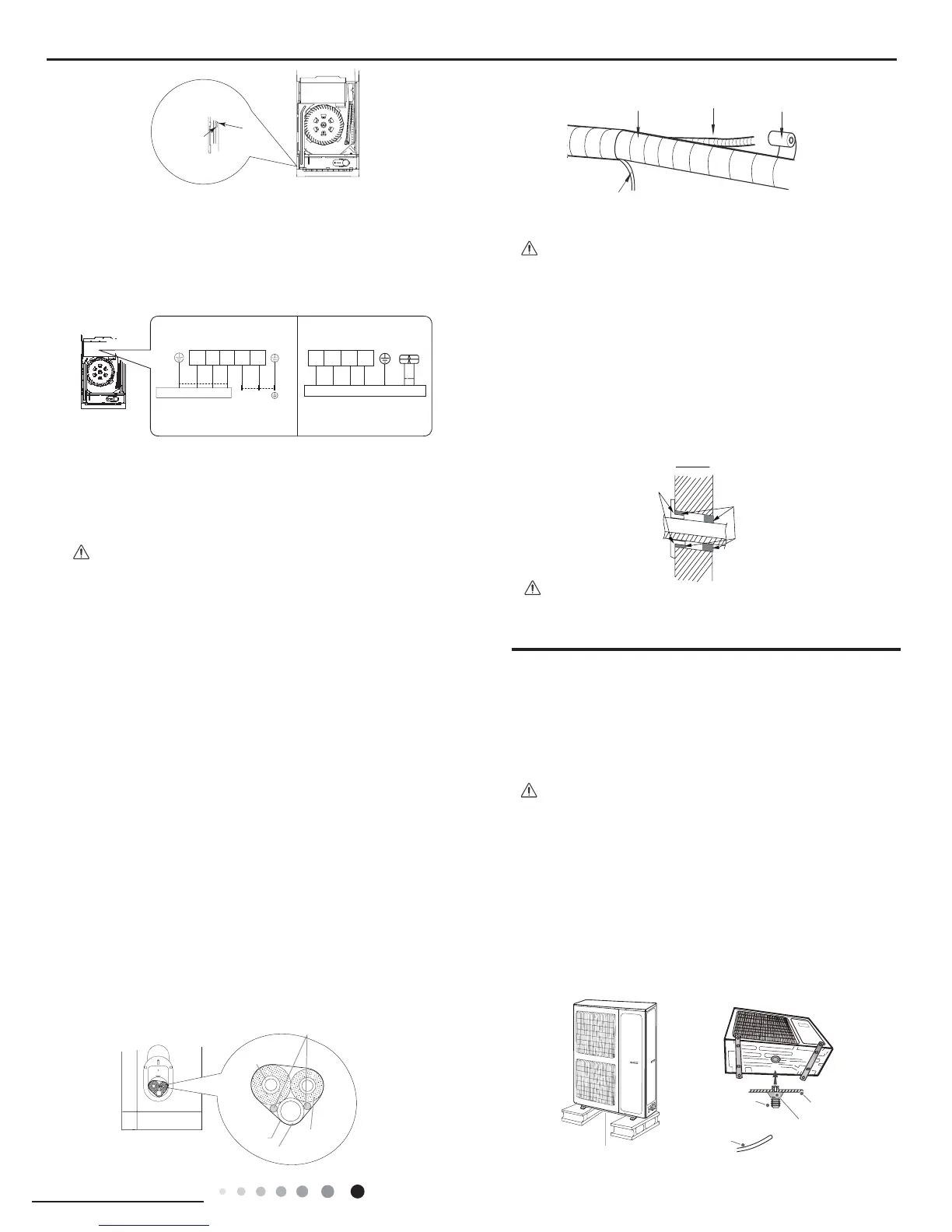
Outdoor unit connection
black
POWER
N
N
L
L
32N(1)
blue bluebrown
brown
yellow-
green
yellow-
green
24K:
48/55K
Outdoor unit connection
L1 L2 L3 N
brown
violet blueblack
yellow-
green
Fig.12
3. Adjust the position of upper and lower adjusting bafe;
clamp the connection pipe and drain pipe as firm as
possible.
4. Tighten the screws.
All wires of indoor unit and outdoor unit should be connected
by a professional.
1.If the length of power connection wire is insufcient, please
contact the supplier for a new one. Avoid extending the wire
by yourself.
2.For the air conditioner with plug, the plug should be
reachable after nishing installation.
3.For the air conditioner without plug, an air switch must be
installed in the line. The air switch should be all-pole parting
and the contact parting distance should be more than 3mm.
Note:
Step seven: bind up pipe
1. Bind up the connection pipe, power cord and drain hose with
the band.(As show in Fig.13)
2.Reserve a certain length of drain hose and power cord for
installation when binding them. When binding to a certain
degree, separate the indoor power and then separate the drain
hose.(As show in Fig.14)
3. Bind them evenly.
4. The liquid pipe and gas pipe should be bound separately at
the end.
Step Eight: place the indoor unit
1.Put the bound pipes in the wall pipe and then make them
pass through the wall hole.
2. Stuff the gap between pipes and wall hole with sealing gum.
(As show in Fig.15)
3. Fix the wall pipe.
4.Check if the indoor unit is installed rmly.
1.The power cord and control wire can't be crossed or winding.
2.The drain hose should be bound at the bottom.
Do not bend the drain hose too excessively in order to
prevent blocking.
indoor unit
gas pipe
Fig.13
Fig.14
Fig.15
Note:
Note:
2. Remove the wire clip; connect the power connection wire
to the wiring terminal according to the color; tighten the screw
and then x the power supply wire,power connection wire with
wire clip.(As show in Fig.12)
(1) Take sufficient protective measures when installing the
outdoor unit.
(2) Make sure the support can withstand at least four times the
unit weight.
(3) The outdoor unit should be installed at least 3cm above the
oor in order to install drain joint.(As show in Fig.18)
(4) For the unit with cooling capacity of 2300W~5000W, 6
expansion screws are needed; for the unit with cooling capacity
of 6000W~8000W, 8 expansion screws are needed; for the
unit with cooling capacity of 10000W~16000W, 10 expansion
screws are needed.
Note:
8.6 Installation of Outdoor Unit
1. Fix the Support of Outdoor Unit(select it according to the
actual installation situation)
(1) Select installation location according to the house structure.
(2) Fix the support of outdoor unit on the selected location with
expansion screws.
Fig.18
Fig.19
chassis
outdoor drain joint
drain hose
drain vent
at least 3cm above the floor

 Loading...