Service Manual
65
Installation and Maintenance
ProcedureStep
6.Remove electric box and wire-passing groove sub-assy
7.Remove air-outlet panel
Remove the three screws at the top and
two screws at the lower part of air outlet
panel and screws in the screw covers
at two sides; push the air outlet panel
upwards slightly to remove the air outlet
panel assy.
Remove the four screws fixing the electric
box cover and then remove the electric box
cover; disconnect the wiring terminal of each
electronic components and then remove
related electronic components according to
your requirements;
1.Remove the two screws fixing the electric
box assy and then lift the electric box assy
outwards to remove it;
2.Remove the four screws xing the cover of
wire-crossing groove and then remove the
cover of wire-crossing groove;
3.Remove the four screws fixing the wire-
crossing groove and then remove the wire-
crossing groove sub-assy.
electric box assy
electric box cover
screws
screws
screws
screws
wire-crossing groove
wire-crossing
groove cover
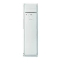
air-outlet panel

 Loading...