EasyManua.ls Logo

Gree GVC24AMXF-K3NTC7A

Gree GVC24AMXF-K3NTC7A
100 pages
To Next Page IconTo Next Page
Loading...
Service Manual
Change for life
GREE ELECTRIC APPLIANCES, INC. OF ZHUHAI

Questions and Answers:

Gree GVC24AMXF-K3NTC7A Specifications

General IconGeneral
RefrigerantR410A
Cooling Capacity24000 BTU
Power Supply220-240V, 50Hz
TypeSplit Type
Air Flow (Indoor)1000 m³/h
Operating Temperature (Cooling)18-43 °C

Summary

Summary of Air Conditioner Models

Indoor and Outdoor Unit Models

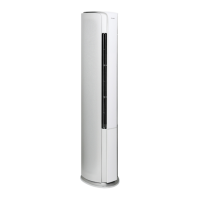
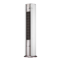
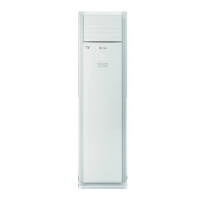
Visual identification and model details for indoor and outdoor units.

Remote Controller Overview

Image and identification of the remote controller.

Air Conditioner Specifications

Indoor Unit Specifications

Detailed technical data for various indoor unit models.

Outdoor Unit Specifications

Detailed technical data for various outdoor unit models.

Capacity Variation and Data Sheets

Graphs and tables for cooling/heating performance at varying conditions.

Outline Dimension Diagrams

Indoor Unit Dimensions

Dimensional drawings and measurements for indoor units.

Outdoor Unit Dimensions

Dimensional drawings and measurements for outdoor units.

Refrigerant System Diagrams

Cooling and Heat Pump Models

Diagrams illustrating refrigerant flow in cooling and heat pump modes.

Electrical Part Diagrams

Wiring Diagram Instructions and Indoor Units

Explanation of wiring symbols and diagrams for indoor units.

Outdoor Unit Wiring Diagrams

Wiring diagrams specific to outdoor units.

Indoor Unit PCB Printed Diagrams

Layout of printed circuit boards for indoor units.

Function and Control

Air Conditioner Button Functions

Names and descriptions of buttons on the air conditioner unit.

Icon Function Introduction

Explanation of various icons displayed on the unit.

Remote Controller Operation

Guide to remote controller buttons and display icons.

Basic Mode Operation Conditions

Conditions for auto, cooling, drying, and heating modes.

Installation and Maintenance Precautions

General Safety Warnings

Crucial safety guidelines for installation and maintenance.

Electrical and Refrigerant Safety

Specific safety rules for electrical work and refrigerant handling.

Installation Procedures

Installation Dimension Diagrams

Diagrams showing required clearances and dimensions for installation.

Installation Procedures Overview

Step-by-step guide for the overall installation process.

Installation Parts Check and Location Selection

Checking parts and choosing the right location for installation.

Electrical Connection and Grounding Requirements

Guidelines for safe electrical connections and grounding.

Maintenance and Troubleshooting

Error Code List

Comprehensive list of error codes and possible causes.

Troubleshooting Common Malfunctions

Guidance for resolving common operational issues.

Exploded Views and Parts Lists

Indoor Unit Exploded Views

Diagrams showing disassembled indoor unit components.

Outdoor Unit Exploded Views

Diagrams showing disassembled outdoor unit components.

Removal Procedures

Indoor Unit Removal Steps

Detailed steps for disassembling indoor units.

Outdoor Unit Removal Steps

Detailed steps for disassembling outdoor units.

Appendices

Temperature Conversion and Pipe Configuration

Temperature conversion chart and connection pipe specifications.

Pipe Expanding Method

Procedure for expanding pipes for proper refrigerant connections.

Temperature Sensor Resistance Tables

Data tables for temperature sensor resistance values.

Related product manuals