42
Installation and Maintenance
Service Manual
8.5 Installation of Indoor Unit
1. Choosing Installation Iocation
Recommend the installation location to the client and then
conrm it with the client.
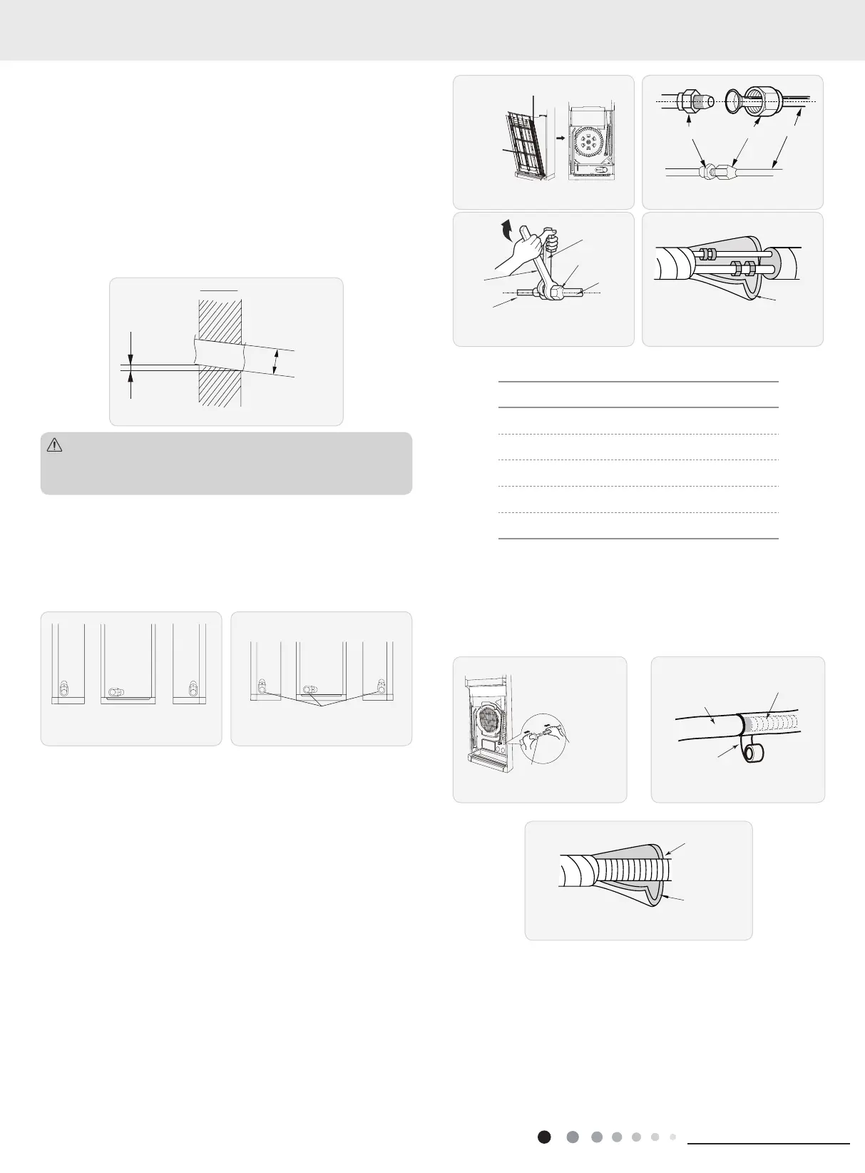
2. Open piping hole
(1) Choose the position of piping hole according to the direction
of outlet pipe.
(2) Open a piping hole with the diameter of Ф70 on the selected
outlet pipe position. In order to drain smoothly, slant the piping
hole on the wall slightly downward to the outdoor side with the
gradient of 5-10°. (As show in Fig.1)
5-10
°
Φ70m
Fig.1
Pay attention to dust prevention and take relevant safety
measures when opening the hole.
Note:
3. Outlet Pipe
(1) The pipe can be led out in the direction of left, right or rear.
(As show in Fig.2)
(2)
After conrming the direction of outlet pipe, loosen the screws
at the upper and lower adjusting bafe to let the connection pipe/
drain pipe connects the indoor unit. (As show in Fig.3)
Fig.2
right
Fig.3
upper and lower adjusting baffle
left back
right
4. Connect the Pipe of Indoor Unit
(1) Take out the left and right screw cover and then remove the
screws on air-inlet panel, push the front door plate upwards and
then separate the connector connected to the connection wire of
display and then remove the front door plate sub-assy. Remove
two screws on the air-in panel sub-assy. Open the air-in panel
along the arrow direction and then remove the air-in panel sub-
assy.(As show in Fig.4)
(2) Aim the pipe joint at the corresponding bellmouth.(As show in
Fig.5)
(3) Pretightening the union nut with hand.
(4) Adjust the torque force by referring to the following sheet.
Place the open-end wrench on the pipe joint and place the
torque wrench on the union nut. Tighten the union nut with torque
wrench.(As show in Fig.6)
(5) Wrap the indoor pipe and joint of connection pipe with
insulating pipe, and then wrap it with tape. (As show in Fig.7)
Union nutPipe joint
Pipe
Fig.5
Fig.4
h
wrench
Pipe
Union nut
Fig.6
Fig.7
Refer to the following table for wrench moment of force
:
Piping size (inch) Tightening torque (N
.
m)
1/4 15~20
3/8 30~40
1/2 45~55
5/8 60~65
3/4 70~75
5. Install Drain Hose
(1) Connect the drain hose to the outlet pipe of indoor unit.(As
show in Fig.8)
(2) Bind the joint with tape.(As show in Fig.8)
(3) Add insulating pipe in the indoor drain hose in order to prevent
condensation.(As show in Fig.10)
drain hose
Outlet pipe
Fig.8 Fig.9
Insulating pipe
Drain hose
Fig.10
6. Connect Wire of Indoor Unit
(1) Make the power connection wire go through the cablecross
hole of indoor unit(As show in Fig.11)
8. Installation
 Loading...