54
Installation and Maintenance
Service Manual
3.Drill piping hole
(1) Choose the position of piping hole according to the direction
of outlet pipe. The position of piping hole should be a little lower
than the wall-mounted frame.(As show in Fig.1)
Fig.1
(2) Drill a piping hole with the diameter of Ф2 11/64"/Ф2 49/64" on
the selected outlet pipe position.In order to drain smoothly, slant
the piping hole on the wall slightly downward to the outdoor side
with the gradient of 5-10°. (As show in Fig.2)
5-10
°
Φ2 11/64
Φ2 49/64
Fig.2
Pay attention to dust prevention and take relevant safety
measures when drill the hole.
Note:
4. Outlet Pipe
(1) The pipe can be led out in the direction of right, rear right, left
or rear left. (As show in Fig.3)
(2) When selecting leading out the pipe from left or right, please
cut off the corresponding hole on the bottom case. (As show in
Fig.4)
Fig.3
Left
Rear lef
Rear right
Fig.4
Cut off
the hole
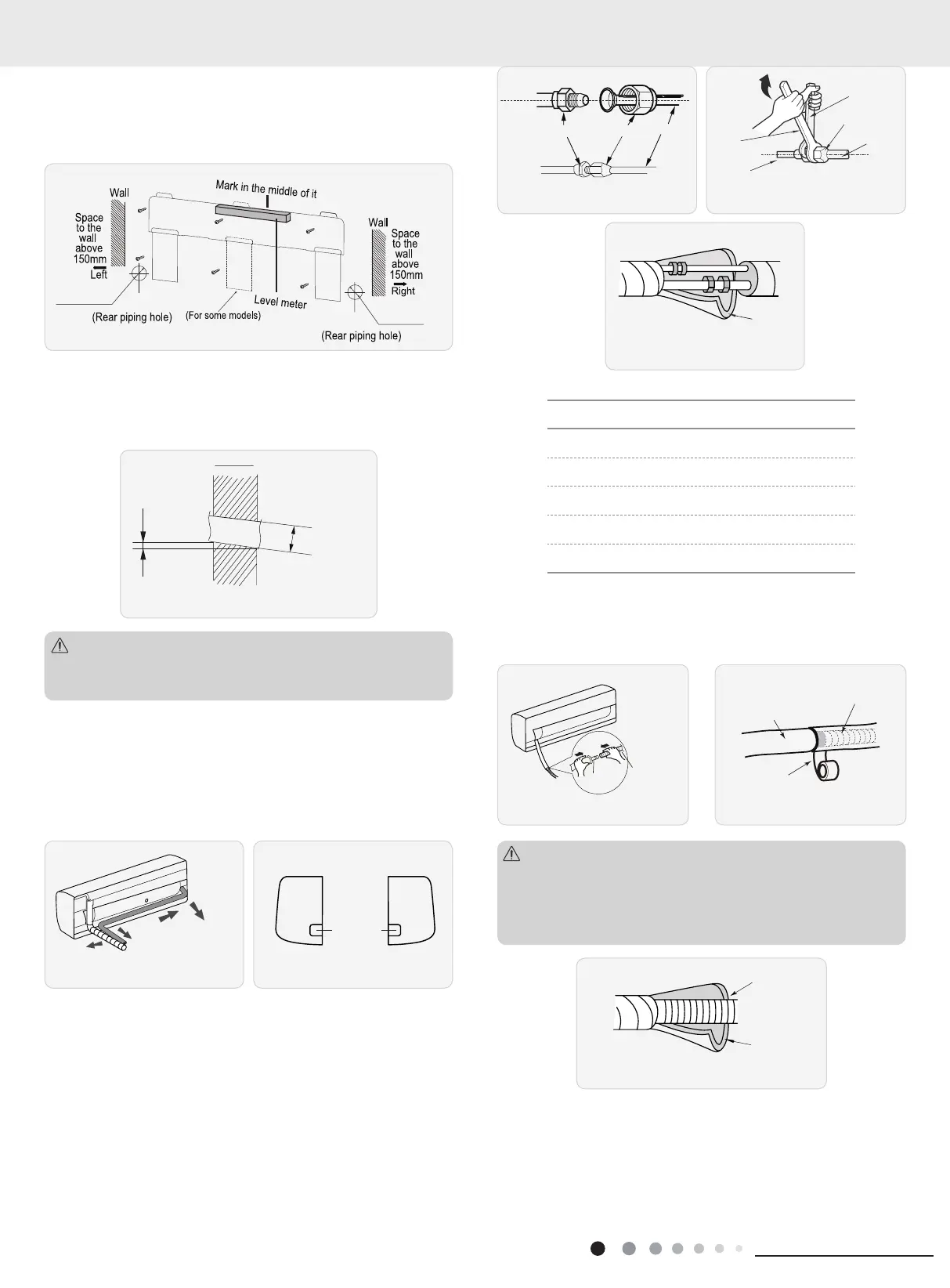
5. Connect the Pipe of Indoor Unit
(1) Aim the pipe joint at the corresponding bellmouth. (As show in
Fig.5)
(2) Pretightening the union nut with hand.
(3) Adjust the torque force by referring to the following sheet.
Place the open-end wrench on the pipe joint and place the
torque wrench on the union nut. Tighten the union nut with torque
wrench. (As show in Fig.6)
(4) Wrap the indoor pipe and joint of connection pipe with
insulating pipe, and then wrap it with tape. (As show in Fig.7)
h
wrench
Pipe
Union nut
pipe joint union nut
pipe
Fig.5 Fig.6
Fig.7
Refer to the following table for wrench moment of force
:
Piping size (inch) Tightening torque (N
.
m)
1/4 15~20
3/8 30~40
1/2 45~55
5/8 60~65
3/4 70~75
6. Install Drain Hose
(1) Connect the drain hose to the outlet pipe of indoor unit. (As
show in Fig.8)
(2) Bind the joint with tape. (As show in Fig.9)
Outlet
pipe
Outlet pipe
Fig.8 Fig.9
(1) Add insulating pipe in the indoor drain hose in order to
prevent condensation.
(2) The plastic expansion particles are not provided.
(As show in Fig.10)
Note:
Insulating pipe
Drain hose
Fig.10
7. Connect Wire of Indoor Unit
(1) Open the panel, remove the screw on the wiring cover and
then take down the cover. (As show in Fig.11)
Ф2 11/64"
Ф2 49/64"
Ф2 11/64"
Ф2 49/64"