L2 G
G
L1
S L2’L1’
L1
L2
L1’SL2’ L2
L2
L1 G
L1
N(1) 2 3 L
L
N
N
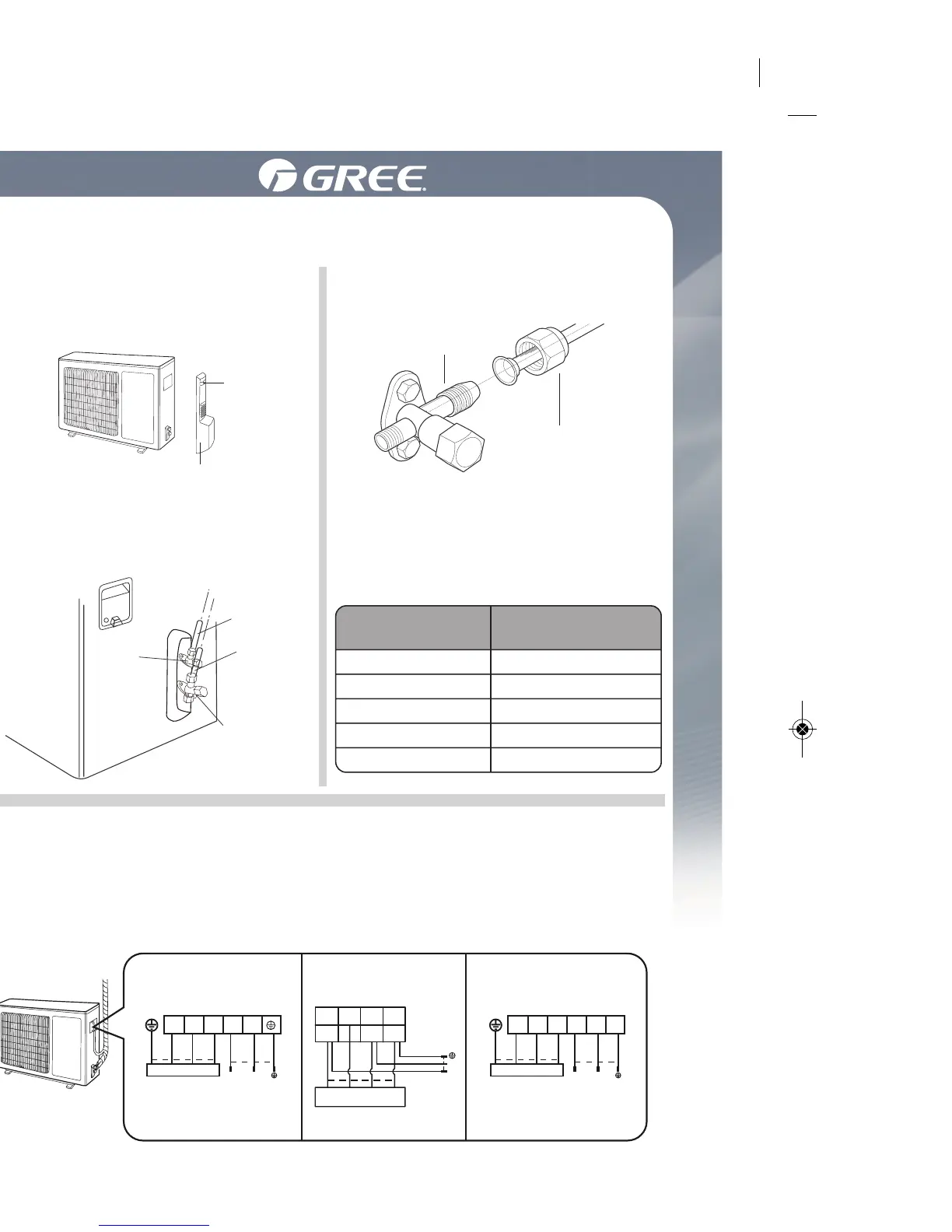
09, 12K(for some model):
Indoor unit connection POWER Indoor unit connection POWER
Indoor unit connection
09, 12K(for some model):
18, 24K
green
(yellow
green)
white
(blue)
white
(blue)
white
(blue)
power
black
black
black
red
(brown)
red
(brown)
red
(brown)
black
(brown)
black
(brown)
white
(blue)
white
(blue)
green
(yellow
green)
green
(yellow
green)
green
(yellow
green)
green
(yellow
green)
green(yellow-green)
black(brown)
white(bue)
Installation of outdoor unit
Step four: connect indoor and outdoor pipes
Step five: connect outdoor eletric wire
1 . Remove the screw on the right
handle of outdoor unit and then
remove the handle.
1. Remove the wire clip; connect the power connection wire and
signal control wire (only for heating unit) to the wiring terminal
according to the color; fix themwith screws.
Note: the wiring board is for reference only, please refer to the
actual one.
Note: le tableau de câblage est seulement un guide; référez-vous à
celui de l’appareil.
3. Pretighten the union nut with
hand.
4. Tighten the union nut with
torque wrench by referring to
the sheet below.
2. Remove the screw cap of valve
and aim the pipe joint at the bell
mouth of pipe.
Screw
Pipe joint
Union nut
Liquid pipe
Gas pipe
Gas valve
Handle
HEX NUT
DIAMETER
TIGHTENING TORQUE
(NM)
Installation de l'unité extérieure
Étape 4: Raccorder les tuyaux intérieurs et extérieurs
Étape 5: Branchement électrique
1. Dévissez et enlevez la poignée
à la droite de l'appareil.
1. Enlevez le serre-câble; connectez le fil d'alimentation et le fil de
transmission (seulement pour les appareils avec chauffage) à la
borne du câble selon la couleur correspondante; solidifiez avec
les vis.
3. Tout d'abord, serrez l'écrou-
union à la main.
4. Resserrez l'écrou-union avec la
clé dynamométrique en vous
référant au tableau ci-bas.
2
. Enlevez le bouchon de la valve
et alignez le joint du tuyau sur
l'orifice évasé du tuyau.
 Loading...