136
Installation and Maintenance
Service Manual
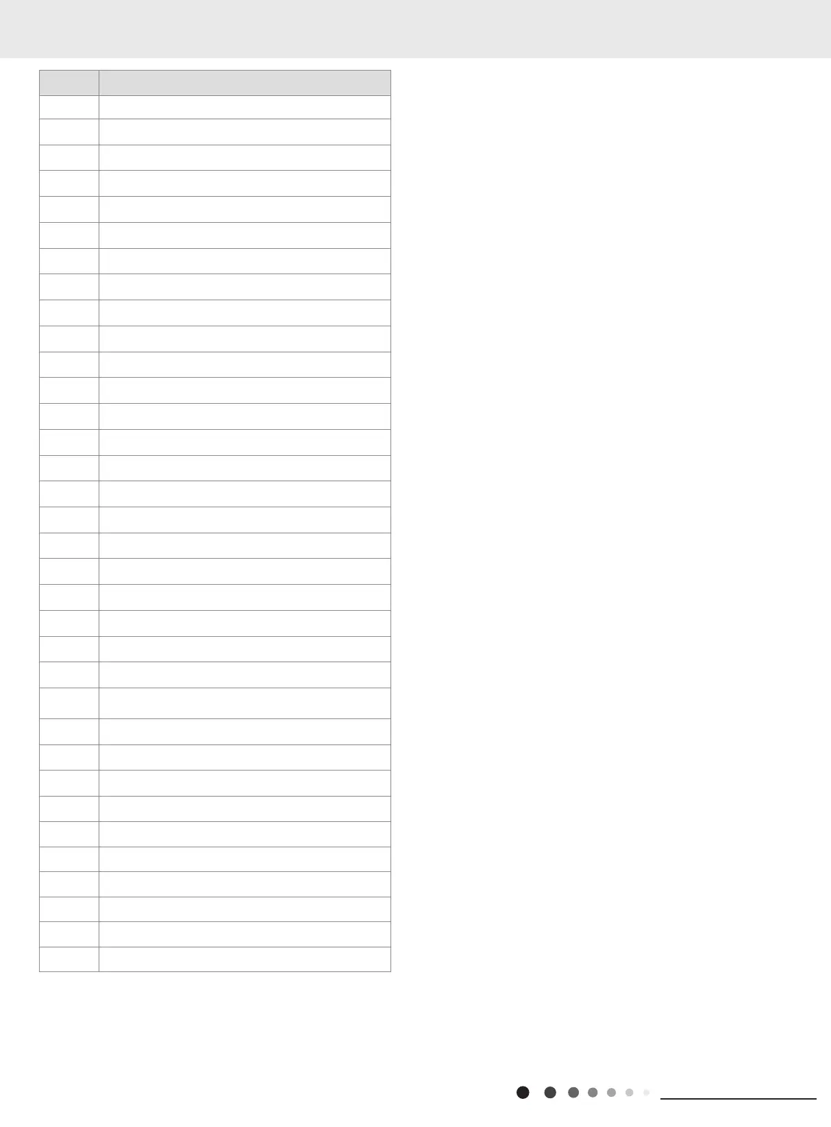
NO. Description
1 Coping
2 Supporting Board(Condenser)
3 4-Way Valve
4 Sponge(Condenser)
5 Temperature Sensor Support
6 Condenser Assy
7 Capillary Sub-assy
8 Sensor Insert
9 Right Side Plate
10 Earthing Plate Sub-assy
11 Wire Clamp
12 Handle Assy
13 Silencer
14 Cut-off valve 1/4(N)
15 Cut-off valve 3/8(N)
16 Valve Support
17 4-Way Valve Assy
18 Compressor and Fittings
19 Chassis Sub-assy
20 Motor Support
21 Brushless DC Motor
22 Axial Flow Fan
23 Cabinet
24 Front Grill
25 Drainage Joint(ODU)
26 Left Side Plate
27 Clapboard
28 Electric Box Assy
29 Electric Box
30 Main Board
31 Electric Box Cover
32 Terminal Board
33 Temperature Sensor
34 Radiator
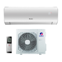
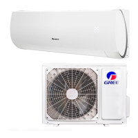
Some models may not contain some parts, please refer to the actual product.
 Loading...