41
Technical Information
Service Manual
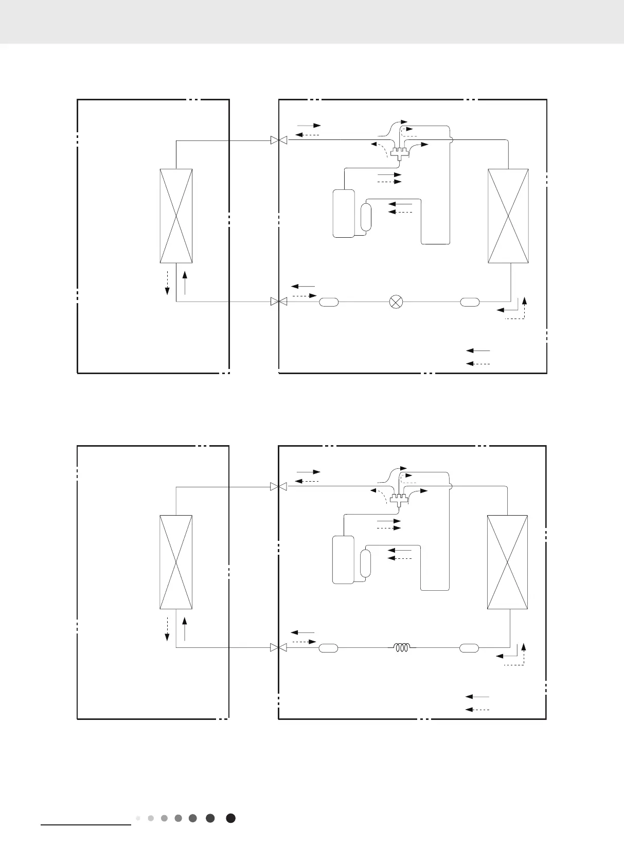
4. Refrigerant System Diagram
GWH12AFC-K6DNA2F/O GWH18AFD-K6DNA2I/O GWH18QD-K6DNA1D/O GWH24QE-K6DNA1E/O
GWH24AFE-K6DNA2I/O
GWH07QA-K6DNC4A/O GWH09AGA-K6DNA1A/O GWH09AFC-K6DNA2F/O GWH12AGB-K6DNA1A/O
GWH24ALD-K6DNA1B/O GWH18ALD-K6DNA1A/O
Connection pipe specication:
Liquid pipe:1/4"
Gas pipe:3/8" (QA/QB/QC/GWH18ALD-K6DNA1A/O)
Gas pipe:1/2" (QD)
Gas pipe:5/8" (QE)
COOLING
4-Way valve
HEATING
Discharge
Suction
Heat
exchanger
(evaporator)
Heat
exchanger
(condenser)
Valve
Valve
side
Liquid pipe
Gas pipe
side
Strainer Electric
expand
valve
Compressor
Accumlator
Strainer
Indoor unit
COOLING
4-Way valve
HEATING
Discharge
Outdoor unit
Suction
Heat
exchanger
(evaporator)
Heat
exchanger
(condenser)
Valve
Valve
side
Liquid pipe
Gas pipe
side
Strainer
Strainer
Capillary
Accumlator
Compressor
 Loading...