96
Installation and Maintenance
Service Manual
(1) After tightening the screw, pull the power cord slightly to check
if it is rm.
(2) Never cut the power connection wire to prolong or shorten the
distance.
Note:
can't raise
upwards.
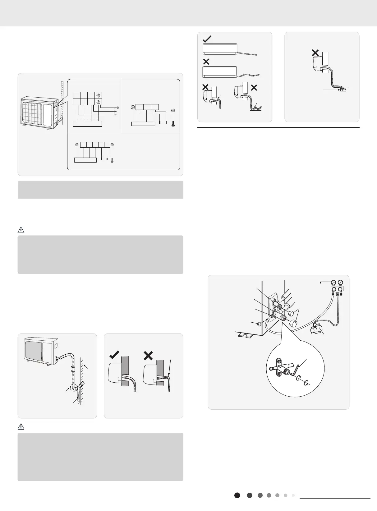
5. Connect Outdoor Electric Wire
(1) Remove the wire clip; connect the power connection wire and
signal control wire (only for cooling and heating unit) to the wiring
terminal according to the color; x them with screws.(As show in
Fig.23)
6. Neaten the Pipes
(1) The pipes should be placed along the wall, bent reasonably and
hidden possibly. Min. semidiameter of bending the pipe is 10cm.
(2) If the outdoor unit is higher than the wall hole, you must set
a U-shaped curve in the pipe before pipe goes into the room, in
order to prevent rain from getting into the room.(As show in Fig.24)
(2) Fix the power connection wire and signal control wire with wire
clip (only for cooling and heating unit).
Fig.23
Fig.24 Fig.25
Indoor unit connection
LN
N(1) 23
L
N
POWER
blue
blue
brown
brown(black)
black
yellow-
green
yellow-green
yellow-
green
N(1)
blue
POWER
2
N
Indoor unit connection
black (black)
L(3)
brown
brown
L
blue
yellow-
green
GWH09AFC-K6DNA2F/O
GWH12AFC-K6DNA2F/O
GWH18AFD-K6DNA2I/O
GWH18ALD-K6DNA1A/O
GWH24ALD-K6DNA1B/O
GWH24AFE-K6DNA2I/O
GWH07QA-K6DNC4A/O
GWH09AGA-K6DNA1A/O
GWH12AGB-K6DNA1A/O
LN
Indoor unit connection
GWH18QD-K6DNA1D/O
GWH24QE-K6DNA1E/O
LN
POWER
N(1)2 3
blue
brown
brown
(black)
blue
yellow-
green
black
yellow-
green
Note: the wiring connect is for reference only,please refer to the
actual one.
U-shaped curve
(1) The through-wall height of drain hose shouldnt be higher than
the outlet pipe hole of indoor unit.(As show in Fig.25)
(2) Slant the drain hose slightly downwards. The drain hose cant
be curved, raised and uctuant, etc.(As show in Fig.26)
(3) The water outlet cant be placed in water in order to drain
smoothly.(As show in Fig.27)
Note:
Liquid valve
Gas valve
Refrigerant charging
vent
Nut of refrigerant
Charging vent
Vacuum pump
Piezometer
Valve cap
Lo Hi
Inner hexagon
spanner
Open
Close
The drain hose can't be fluctuant
The drain
hose can't
be fluctuant
The water
outlet can't
The water outlet
can't be placed
in water
1. Use Vacuum Pump
(1) Remove the valve caps on the liquid valve and gas valve and
the nut of refrigerant charging vent.
(2) Connect the charging hose of piezometer to the refrigerant
charging vent of gas valve and then connect the other charging
hose to the vacuum pump.
(3) Open the piezometer completely and operate for 10-15min to
check if the pressure of piezometer remains in -0.1MPa.
(4) Close the vacuum pump and maintain this status for 1-2min
to check if the pressure of piezometer remains in -0.1MPa. If the
pressure decreases, there may be leakage.
(5) Remove the piezometer, open the valve core of liquid valve
and gas valve completely with inner hexagon spanner.
(6) Tighten the screw caps of valves and refrigerant charging
vent.(As show in Fig.28)
8.7 Vacuum Pumping and Leak Detection
Fig.26 Fig.27
Fig.28
2. Leakage Detection
(1) With leakage detector:
Check if there is leakage with leakage detector.
(2) With soap water:
If leakage detector is not available, please use soap water for
leakage detection. Apply soap water at the suspected position and
keep the soap water for more than 3min. If there are air bubbles
coming out of this position, there's a leakage.
 Loading...