143
Installation and Maintenance
Service Manual
11. Removal Procedure
Step Procedure
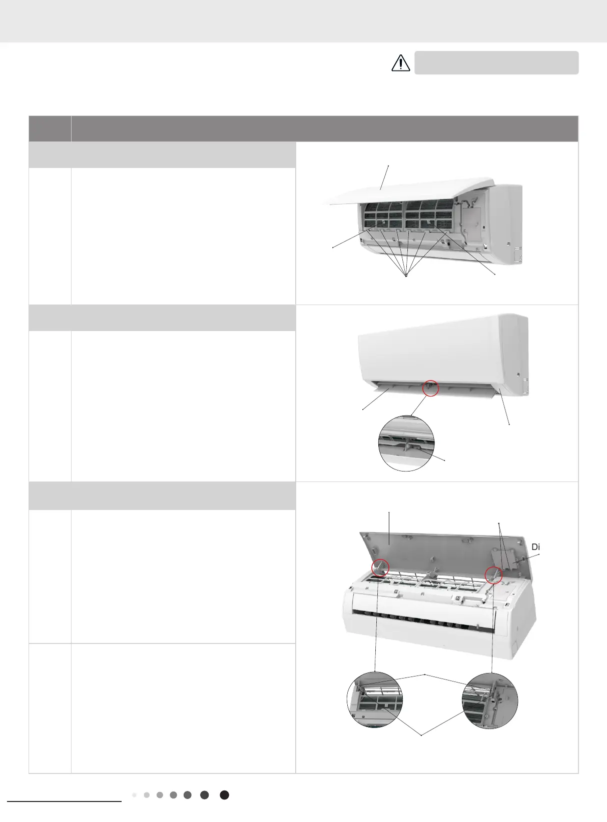
1.Remove lter assembly
Open the front panel. Push the left lter and right lter
until they are separate from the groove on the front
panel.
Remove the left lter and right lter respectively.
2. Remove horizontal louver
Push out the axile bush on horizontal louver. Bend
the horizontal louver with hand and then separate the
horizontal louver from the crankshaft of step motor to
remove it.
3. Remove panel
a
①
A1/B6/C2/C4 display: Screw off the 2 screws that
are locking the display board. Separate the display
board from the front panel.
②
A2/A3 display: Screw off the 2 screws that are
locking the display board. This display can be
disassembled only after removing the front case (refer
to step 5 of disassembly).
③
A5/B2/B4/B8/C6/D2 display: Screw off the 2 screws
that are locking the display board.
b
Separate the panel rotation shaft from the groove xing
the front panel and then removes the front panel.
Axile bush
Front panel
Screws
Display
Horizontal louver
Location of step motor
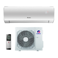
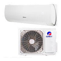
11.1 Removal Procedure of Indoor Unit
Caution: discharge the refrigerant
completely before removal.
Groove
Right lter
Front
case
Front panel
Left lter
Panel rotation
Groove
 Loading...