98
Installation and Maintenance
Service Manual
panel display
Screws
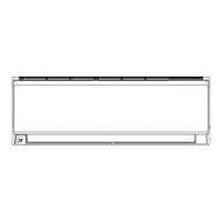
4. Remove electric box cover 2 and detecting plate(WIFI)
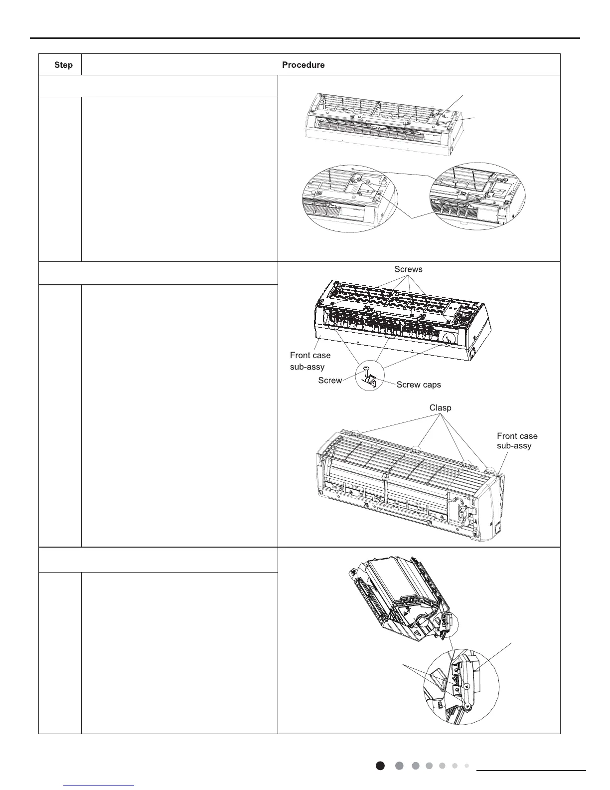
5.Remove front case sub-assy
6.Remove display
Remove the screws on the electric box
cover 2 and detecting plate(WIFI), then
remove the electric box cover 2 and
detecting plate(WIFI).
Remove the screws xing front case.
Note:
①
Open the screw caps before removing the
screws arround the air outlet.
②
The quantity of screws xing the front
case sub-assy is different for different
models.
Loosen the connection clasps between front
case sub-assy and bottom case. Lift up the
front case sub-assy and take it out.
Screw off the 2 screws that are locking the
display board.
a
b
 Loading...