Do you have a question about the Gree ME30-24/E6M and is the answer not in the manual?
Covers essential safety, installation, and operational advice for correct product usage and to avoid hazards.
Details potential damages from non-compliance, prohibited actions, and necessary observations for safe operation.
Emphasizes qualified personnel for installation, precautions against electric shock, and proper use of power cables.
Explains the gateway's role in data exchange and lists compatible air conditioning models.
Details the specific items contained within the product package for user reference.
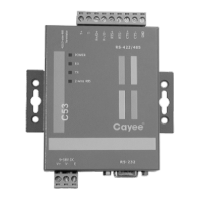
Covers the different interfaces available on the gateway, including function drawings, power, and communication ports.
Details the meaning of each LED indicator (Power, CAN, RS485 TX/RX) for operational status feedback.
Explains the various DIP switch settings for the gateway, including address, CAN2 bus, Modbus bus, and IDU project number configurations.
Provides product dimensions and recommended installation space within an electric control cabinet for proper mounting.
Specifies the material, length, and diameter requirements for communication cables used with the gateway.
Details the required connection methods (series connection) and provides diagrams for BMS and air conditioner communication.
Provides step-by-step instructions for connecting the gateway to BMS and air conditioners, including DIP settings.
Explains how the gateway integrates with BMS using the Modbus protocol and lists compatible HVAC systems.
Illustrates system network topologies and provides explanations for Modbus, CAN1, and CAN2 networks.
Contains detailed tables mapping DIP switch configurations to specific addresses for various ranges.