EasyManua.ls Logo

Gree ME30-24/E5 User Manual

Gree ME30-24/E5
28 pages
To Next Page IconTo Next Page
Page #1 background imageLoading...
Page #1 background image
Owner's Manual
Original Instructions
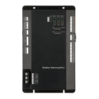
Modbus Gateway(Pro)
Models:ME30-24/E5(M)

Other manuals for Gree ME30-24/E5

Questions and Answers:

Gree ME30-24/E5 Specifications

General IconGeneral
BrandGree
ModelME30-24/E5
CategoryGateway
LanguageEnglish

Summary

Safety Notices

Safety Warning Symbols

Explains warning symbols indicating prohibition or required observation.

Environmental Installation Warnings

Warns against installing in corrosive or flammable environments, risks.

Product Functionality

General Functions

Describes the purpose and capabilities of the Modbus Gateway.

Product Composition

Package Contents

Lists the included items: Modbus Gateway(Pro) and Owner's Manual.

Device Interfaces

Interface Function Drawing

Diagram showing the location and purpose of various interfaces.

Power Specifications

Details the input power specifications and safety precautions.

Device Interfaces

Communication Interfaces

Describes CAN, RS485, RS232, Ethernet, USB/SD interfaces.

Device Interfaces

Digital Input/Output (DI/DO)

Explains digital inputs (DI) and digital outputs (DO) functionality.

Device Indicators and Controls

LED Display Meanings

Explains the meaning of various LED indicators on the device.

DIP Switch Introduction

Introduces the two types of DIP switches: address and function.

DIP Switch Configuration

DIP Switch Diagram

Illustrates the positions (0/1) and direction of DIP switches.

Address DIP Switch Settings

Explains how to set the device address using DIP switches.

DIP Switch Configuration

Modbus Bus Matched Resistance

Details setting the 7th DIP switch for Modbus bus matched resistance.

DIP Switch Configuration

CAN2 Bus Matched Resistance

Details setting the 8th DIP switch for CAN2 bus matched resistance.

Application Scenarios

Building Management System (BMS)

Explains the gateway's use as an interface for BMS.

Application Scenarios

Network Topology Diagram

Illustrates the network topology for BMS integration.

Topology Definitions

Defines Modbus bus, CAN1, CAN2 networks, and system components.

Installation Guide

Product Dimensions

Shows the physical dimensions of the Modbus Gateway(Pro).

Installation Guide

Cabinet Installation Space

Specifies the required space for installing the gateway in a cabinet.

Communication Cable Specifications

Details the specifications for communication cables.

Communication Connection Methods

Serial Connection Requirement

Emphasizes that all communication cables must be connected in series.

BMS Connection Diagram

Illustrates serial connection for Modbus to BMS communication.

Air Conditioner Connection Diagram

Illustrates serial connection for Modbus to air conditioner communication.

Communication Connection Settings

BMS Wiring Steps

Step-by-step guide for connecting Modbus Gateway to BMS.

Air Conditioner Wiring Steps

Step-by-step guide for connecting Modbus Gateway to air conditioners.

Communication DIP Switch Setup

Instructions for setting DIP switches for communication parameters.

Communication Connection Settings

Modbus Bus Repeater Guidelines

Guidelines for using photoelectric isolation repeaters for Modbus bus.

DIP Address Tables

Address Table 0-31

Table mapping DIP switch settings to addresses 0-31.

Address Table 32-63

Table mapping DIP switch settings to addresses 32-63.

DIP Address Tables

Address Table 64-95

Table mapping DIP switch settings to addresses 64-95.

Address Table 96-127

Table mapping DIP switch settings to addresses 96-127.

DIP Address Tables

Address Table 128-159

Table mapping DIP switch settings to addresses 128-159.

Address Table 160-191

Table mapping DIP switch settings to addresses 160-191.

DIP Address Tables

Address Table 192-223

Table mapping DIP switch settings to addresses 192-223.

Address Table 224-255

Table mapping DIP switch settings to addresses 224-255.

Related product manuals