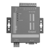
Modbus Gateway(Pro)
13
6.1.2 Installation Space of Electric Control Cabinet
Modbus Gateway(Pro) shall be installed in the electric control cabinet. The
front side of gateway shall be hung upwards and secured by four screws. Required
installation space is shown as below (only for reference).
Secure
it by four
screws
296mm
177mm
With the front side
hung upwards
120mm 120mm 120mm
50mm
Wire groove
120mm 120mm
98.5mm
Electric control
cabinet
120mm
Wire groove
6.2 Communication Connection
Communication system of Modbus Gateway(Pro) includes:
(1) Communication between Modbus Gateway(Pro) and BMS;
(2) Communication between Modbus Gateway(Pro) and air conditioner.
6.2.1 Material Selection of Communication Cable
Modbus Ga
Communicat
ion between
Modbus
Gateway(Pr
o) and BMS
Light/Ordinar
y PVC
sheathed
twisted pair
copper
wire(60227
IEC52/60227
IEC53)
When
communication
distance
exceeds 800m,
photoelectric
isolation
repeater shall
be added
Communicat
ion between
Modbus
Gateway(Pr
o) and air
conditioner
Light/Ordinar
y PVC
sheathed
twisted pair
copper
wire(60227
IEC52/60227
IEC53)
The length of
communication
cable shall not
exceed 500m