Modbus Gateway(Pro)
6
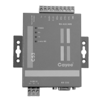
4.2 LED display
LED indicators shown in the above figure are divided into two parts: status
indicators (operation, alarm, power) and communication indicators(CAN, RS485,
RS232). Operation status of each indicator is shown in the following table.
When the data from the equipment (e.g. air conditioner)
connected with Modbus Gateway(Pro) is received, it will
flash.
When the data is transferred to the equipment (e.g. air
conditioner) connected with Modbus Gateway(Pro), it
will flash.
When the data from the Modbus bus is received, it will
flash.
When the data is transferred to the Modbus bus, it will
flash.
This device does not use this LED indicator.
This device does not use this LED indicator.
This device does not use this LED indicator.
This device does not use this LED indicator.
When power supply of Modbus Gateway(Pro) is normal,
it will be always on..
When Modbus Gateway(Pro) works normally, it will
blink.
This device doesn’t use this LED indicator.
4.3 DIP Switches
Notice! Please set DIP switches before using this device, otherwise this device
cannot operate normally!
This gateway includes two kinds of DIP switches, address DIP switch and
function DIP switch.