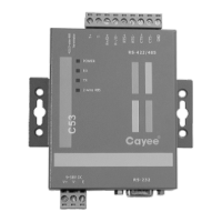
EasyManua.ls Logo

Gree VRF User Manual

Gree VRF
31 pages
To Next Page IconTo Next Page
Page #1 background imageLoading...
Page #1 background image
VRF Protocol Gateway

Questions and Answers:

Gree VRF Specifications

General IconGeneral
BrandGree
ModelVRF
CategoryGateway
LanguageEnglish

Summary

User Notice

Chapter 1 Installation

Introduction to System

Explains the system overview and the gateway's role in data exchange between air conditioners and BMS.

Introduction to Parts

Details the components included in the VRF Protocol Gateway kit and their functions.

Parts List

Lists the components of the VRF Protocol Gateway kit, including models, material codes, and remarks.

Gateway ME30-24/D1(BM)

Details the functions and specifications of the ME30-24/D1(BM) VRF Protocol Gateway.

Gateway and Interface Diagram

Provides a visual diagram of the gateway's physical layout and its various input/output interfaces.

Gateway Kit Components

Lists the specific components included in the VRF Protocol Gateway kit.

Gateway Interfaces

Explains the function and usage of each interface port on the gateway, including power and communication.

Optical Isolation Converter

Explains the function of the optical isolation converter in signal conversion for RS232 and RS485.

Converter Functions

Details the role of the optical isolation converter in converting RS232 signals to RS485 signals.

Converter Outline

Presents an overview diagram of the optical isolation converter.

Converter Interface and Indicators

Describes the interfaces and indicator lights on the optical isolation converter and their usage.

Converter Dimensions

Provides the physical dimensions of the optical isolation converter.

Converter Installation Notices

Details important warnings and recommendations for installing the optical isolation converter.

Optical Isolation Relay

Introduces the function of the optical isolation relay for long-distance communication.

Relay Functions

Explains how the optical isolation relay ensures signal integrity over long distances and supports multiple nodes.

Relay Outline

Presents an overview diagram of the optical isolation relay.

Relay Interface and Indicators

Describes the interfaces and indicator lights on the optical isolation relay and their usage.

Relay Dimensions

Provides the physical dimensions of the optical isolation relay.

Relay Installation Notices

Details important warnings and recommendations for installing the optical isolation relay.

Product Size

Shows the physical dimensions of the VRF Protocol Gateway in millimeters.

Cabinet Installation Space

Describes the spatial requirements and mounting method for installing the gateway in an electric control cabinet.

Modbus RTU Communication Setup

Details the setup for Modbus RTU communication between the gateway and BMS.

Communication Material Selection

Specifies the required communication cable material, diameter, and standard for Modbus bus connection.

Gateway-AC Connection Method

Illustrates the correct serial connection method for communication between the gateway and air conditioners.

Communication Connection Setup

Provides step-by-step instructions for connecting gateways to the BMS terminal using RS485 communication.

Modbus TCP/BACnet Communication Setup

Details the setup for Modbus TCP or BACnet communication between the gateway and BMS.

Network Cable Material

Specifies the types of network cables for connecting the gateway to BMS and air conditioners.

Gateway-BMS Connection Method

Illustrates the connection method between the gateway and BMS via a router.

Communication Connection Configuration

Details the connection configuration for gateway to PC and gateway to AC units.

Gateway Configuration

Explains how to set gateway parameters like IP address, user name, and password.

Chapter 2 Commissioning Operation

Hardware Commissioning

Guides through the hardware commissioning steps, including DIP switch settings.

DIP Switch Settings

Explains the function and settings of the DIP switches for gateway configuration.

LED Indicators

Describes the meaning and status of the LED indicators on the gateway for operational feedback.

Buttons

Explains the function of the SHT/DWN and BACKUP buttons on the gateway.

Communication Commissioning

Provides procedures for commissioning communication with air conditioning equipment and BMS.

AC Communication Commissioning

Details the step-by-step process for commissioning communication with air conditioning units.

BMS Communication Commissioning

Instructs on commissioning communication with BMS equipment using Modbus RTU or TCP/BACnet protocols.

Modbus RTU BMS Communication

Outlines the parameters and steps for Modbus RTU communication between the gateway and BMS.

Modbus TCP/BACnet BMS Communication

Outlines the steps for Modbus TCP or BACnet communication between the gateway and BMS.

Troubleshooting

Provides guidance on diagnosing and resolving common communication issues with the gateway.

Chapter 3 Maintenance

BMS Common Error Troubleshooting

Lists common BMS communication errors, their possible causes, and troubleshooting steps.

Attachment A TCP/IP Setting

Related product manuals