Gree VRF Protocol Gateway
6
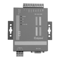
2.3.2 Outline
Note: The picture is for reference only.
2.3.3 Instruction of interface and indicator
1 Power interface Input 12VDC800mA
Self-provided power
2
A wire of RS485 connect to 485 terminal R+, B wire
connects to R
-
See the instruction
manual
3 Power indicator Constantly on when energized
See the instruction
4
TX and RX indicators flash when the communication is
normal
See the instruction
manual