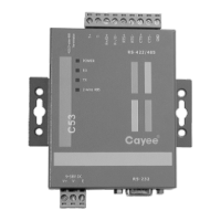
Modbus Gateway(Pro)
5
4.1.4 DI/DO Digital Input/Output
This gateway supports 5 DIs(digital inputs) and 5 DOs(digital outputs); DO6 is
reserved.
DI1...DI5
Digital inputs: 0/1 digital signals(binary system), applicable for those with
power supply
DI1: in CAN2 network, fire alarm signal, connect “1” to the power of 12V,
input fire alarm signal “1” in DI 1 port, then Modbus gateway(Pro) will
give out control, all units stop operation immediately;disconnect “1” or
connect to “0”, input signal “0” in DI 1 port,resume operation of all
ODUs.
In CAN1 network, fire alarm signal, connect “1” to the power of 12V,
input fire alarm signal “1” in DI 1 port, then Modbus gateway(Pro) will
give out control, all units stop operation immediately;disconnect “1” or
connect to “0”, input signal “0” in DI 1 port,resume operation of IDUs
manually.
DI2...DI5: Defined by the user.
DO1...DO5 digital outputs: Relay output, normally-open contact
Max admissible power: 250VAC, 3A; 30VDC, 3A
Example: write “1” into DO5 of Modbus protocol and the two contacts of DO5
relay will be closed; write “0” into DO5 of Modbus protocol and
the two contacts of DO5 relay will be cut off.