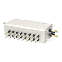
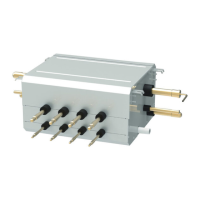
GMV6 HR Mode Exchange Box
23
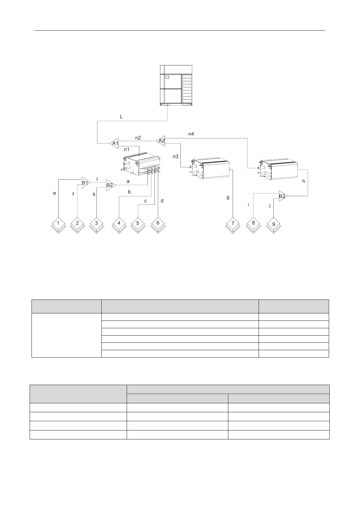
4.2.7 Size Requirement for Branch Pipe and Piping
Take the connection sketch map of single-module system for example.
Fig.4.2.17
4.2.7.1 Branch Selection of Mode Exchange Box (“A1, A2”)
Select branch of Mode Exchange Box as per total capacity of downstream indoor unit(s).
Please refer to the following table.
Model selection for branch “A1
、
A2” of Mode Exchange Box
;
R410A refrigerant system Total capacity of the downstream indoor unit X(kW) Model
Y-Type Branch Pipe
4.2.7.2 Connection for Single Indoor Unit with Capacity of less than 16kW
Piping size among downstream branches of Mode Exchange Box “a
、
h
、
l”
Total rated capacity of downstream
indoor units: X (kW)
Piping size among downstream branches of mode exchange box
Gas pipe/mm Liquid pipe/mm
X≤2.8 Φ9.52 Φ6.35
2.8<X≤5 Φ12.7 Φ6.35
5<X≤14 Φ15.9 Φ9.52
Each branch is to connect to a set of indoor units with the same mode. For the branch does not
connect to indoor unit, make sure that the welding is reliable without leaking of refrigerant.
Branch selection of downstream indoor unit of Mode Exchange Box (“B1
、
B2
、
B3”)