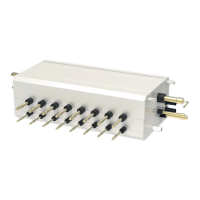
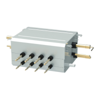
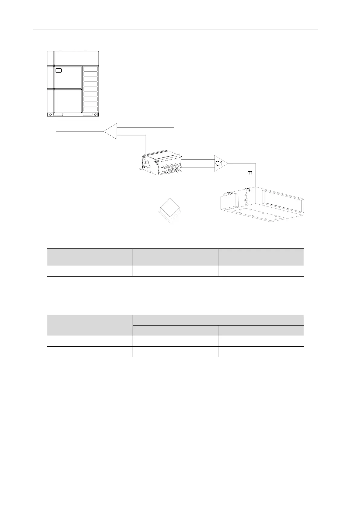
GMV6 HR Mode Exchange Box
25
Connecting method is as shown in the picture:
Fig.4.2.18
4.2.7.4 Branch selection of indoor unit of Mode Exchange Box (“C1”)
R410A refrigerant system
capacity of downstream indoor
units: X/kW
Model
Y-type branch 16<X≤28 FQ01B/A
Size of connection pipe between indoor branch and indoor unit should be consistent with the
connection pipe of indoor unit.
Piping between indoor branch and indoor unit “m”
Rated capacity of indoor units:
C(kW)
Size of connection pipe between indoor branch and indoor unit
Gas pipe/mm Liquid pipe/mm
16<C≤22.4 Φ19.05 Φ9.52
22.4<C≤28 Φ22.2 Φ9.52
4.3 Installation and Test for Drainage Hose
4.3.1 Precautions for the Installation of Drainage Hose
(1) It is not allowed to connect the condensate drain pipe into waste pipe or other pipelines which
are likely to produce corrosive or peculiar smell to prevent the smell from entering indoors or
corrupt the unit.
(2) It is not allowed to connect the condensate drain pipe into rain pipe to prevent rain water from
pouring in and cause property loss or personal injury.
(3) Condensate drain pipe should be connected into special drain system for air conditioner.
(4) As for the drainage hose, the shorter the better. The drainage hose should be kept 1%
~
2%
at least gradient for draining out the condensate water.